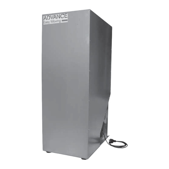
ADVANCE Easy Moving M-TANK Manuel d'assemblage, d'utilisation et d'entretien - Page 8
Parcourez en ligne ou téléchargez le pdf Manuel d'assemblage, d'utilisation et d'entretien pour {nom_de_la_catégorie} ADVANCE Easy Moving M-TANK. ADVANCE Easy Moving M-TANK 17 pages.

Motorized Tank
7 INSTALLATION
It is the installer's responsibility to verify the presence of any risk of danger in the installation
area and to determine the suitability in accordance with both the applicable laws and the product
characteristics described in this manual.
Only specialized technical personnel are authorized to do the installation and maintenance of the product.
All operations must be carried out following the accident prevention regulations and in compliance with
safety warnings.
If you fi nd any damage, anomalies or shortcomings in the product, do not proceed with the installation
and immediately contact your dealer.
The motorized tank must be installed in a covered place, where the temperature is between 0 and 40
° C and the relative humidity is between 40 and 80%, it must not be placed on damp walls and must
not be exposed to the elements, it must be installed levelled and placed on a solid and smooth fl oor to
facilitate the adjustment of the feet.
The motorized tank must be connected to the fuel release dispenser (accessory on request) (see fi gure
1) using rigid or fl exible antistatic pipes, the pipes must have the minimum number possible of elbows,
they should have a minimum radius of 30 cm, while the maximum vertical gap allowed for the fuel transport
pipe is 3 m and the total length of the pipes must not exceed 5 m (each).
All hose connections and junctions must be closed with steel hose clamps to ensure a perfect airtight seal.
Before fi nally positioning the storage unit, complete it by fi tting the sensor, already equipped with a
fl ange, by inserting it into the hole on the side of the storage unit, inserting the sealing gasket (see fi gure
6). Also install the four adjustable feet in their respective threaded inserts on the bottom of the warehouse.
The dispenser (accessory on request, see fi gure 5) must be installed on the boiler tank to refi lled. The
magnetic contact sensor called REED, applied to the dispenser's exhaust door,
via an electrical connection to the motorized warehouse, will check the correct functioning of the conveyor
system. The magnetic contact sensor will also ensure that the fuel transport system is turned off if the tank
to be refi lled is full (see the dispenser instruction manual).
8 PIPES CONNECTION
For connections between the motorised tank and the dispenser, it is essential to use rigid steel or fl exible
pipes with an internal diameter of 50 mm. All pipe junctions must be sealed airtight and must therefore
be carefully tightened. No oblique sections, only vertical or horizontal sections should be made. Very
long sections must be carefully fi xed to the wall or to resistant supports; all elbows must have a minimum
radius of 30 cm. Connect the Ø 50 mm pipe from the OUT outlet to the connection on the dispenser
called OUT, connect the Ø 50 mm pipe from the IN outlet to the connection on the dispenser called IN.
Fuel will fl ow through the IN pipe, while only air and dust will fl ow through the OUT pipe.
All the pipe sections used for the transport system must be antistatic in order to guarantee the effective
dispersion of static currents and must be connected to an grounding point in the electrical system (see
fi gure 1). The grounding point of the motorised tank (see fi gure 2) must be connected to an grounding
point of the electrical system.
fi gure 1
8
fi gure 2
OUT air outlet
Grounding point
IN fuel intake
15/12/21 Rev:1.0.1
