dafi IPX4 Manuel d'utilisation - Page 5
Parcourez en ligne ou téléchargez le pdf Manuel d'utilisation pour {nom_de_la_catégorie} dafi IPX4. dafi IPX4 13 pages. Electric a flow heater with an open outlet water
Également pour dafi IPX4 : Instructions pour l'installation et l'utilisation (12 pages)

The heater must be earthed.
The connection to the wiring system must be ensured by an electrician
provided with an appropriate licence. The heater must be connected
to the wiring system performed only in the TN-S or TN-C-S network
system (according to 0), with copper wires and cross-section corre-
sponding to the rated current of the heater. The wiring system must be
equipped with the switch, that allows the voltage at all poles from the
power source to be disconnected
The overload protection of the electrical network during the installa-
tion of the DAFI electrical flow water heater must be selected in ac-
cordance with the rated current of the heater, given in the table with
parameters.
Note!
If the power cord is damaged, it should be replaced by an appropria-
te cord available at the manufacturer or at the network of authorised
service centres.
Each percent of voltage drop below the rated voltage value decreases
the heating efficiency by about 2%, and therefore, it decreases the
water heating effect.
7. Installation and operation
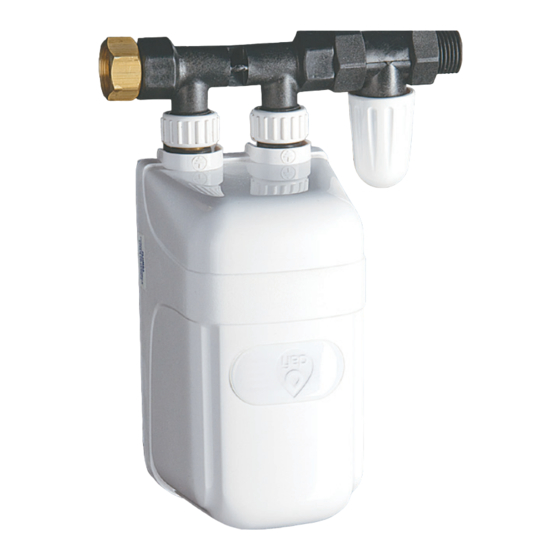
The DAFI water heater may be installed with its own tap, with the connection and
reducing nipples. In the case of installation with the connection and nipples, it is
recommended to install the DAFI shut-off valve at the water inlet to the heater. If the
valve is included in the set, it may be purchased in the retail network.
NOTE! The heater cannot be mounted in rooms, where temperature falls below 1°C.
7.1 Installation of the heater with its own tap
a) For the purpose of installation, use only the installation wrench included
as part of the equipment. Before proceeding with the installation, close the
main water valve and clean the threads. Seal the G ½" thread of the tap body
with the locknut screwed on it, using the teflon tape (fig. 2), and then screw
it into the fitting protruding from the wall, in order to have the two stub pipes
for fixing the heating unit directed vertically upwards.
b) while screwing the tap, maintain particular caution so as not to strip the
thread. Do not screw in the tap while holding the knobs with both hands The
correct method of screwing in the tap is shown in fig. 3.
c) The Distance between the face of the nut and the fitting should be 1-4
mm. After establishing the position and distance of the tap, lock the nut by
tightening it in the direction of the fitting protruding from the wall (fig. 4).
d) Screw the spout to the tap, screw the fixing nut onto the right stub pipe of
the tap (M 18x2), check whether both tap valves are turned off, turn on the
