Baumer PMG10P Instructions de montage et d'utilisation - Page 16

Parcourez en ligne ou téléchargez le pdf Instructions de montage et d'utilisation pour {nom_de_la_catégorie} Baumer PMG10P. Baumer PMG10P 36 pages. Absolute encoder
Également pour Baumer PMG10P : Instructions de montage et d'utilisation (32 pages), Instructions de montage et d'utilisation (32 pages), Manuel d'utilisation (44 pages), Manuel d'utilisation (44 pages), Manuel d'utilisation (40 pages), Manuel d'utilisation (40 pages), Manuel d'utilisation (40 pages), Manuel d'utilisation (36 pages)
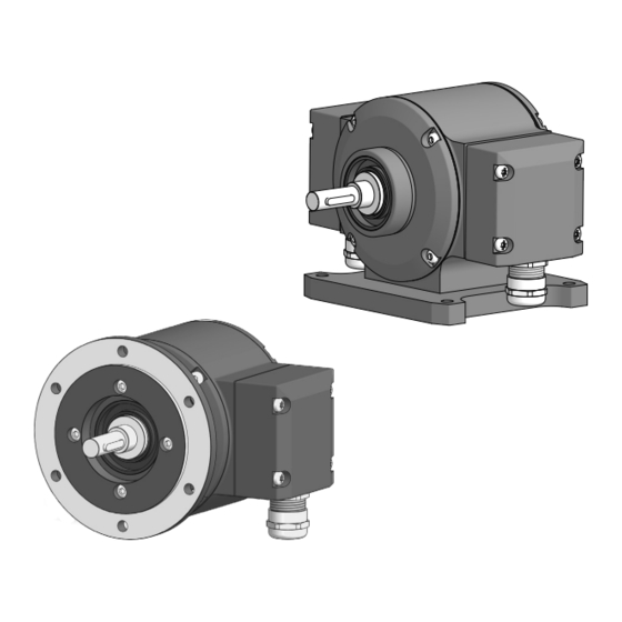
Baumer PMG10P Instructions de montage et d'utilisation
ELECTRICAL CONNECTION / TERMINAL SIGNIFICANCE
5.

ELECTRICAL CONNECTION

5.1

Terminal significance

Ub
0V
A+
1)
A−
1)
B+
1)
B−
1)
R+
1)
R−
1)
nE+
nE−
PRE
DIR
SP+
2)
SP−
2)
SA
3)
SB
3)
D+
D−
C+
C−
dnu
* Depending on version
Additional output incremental (option)
1)
Speed switch (option)
2)
Programming interface (only PMG10P)
3)
13/29
Voltage supply
Ground
Output signal channel 1
Output signal channel 1 inverted
Output signal channel 2 (offset by 90° to channel 1)
Output signal channel 2 inverted
Zero pulse (reference signal)
Zero pulse inverted
System OK+ / error output
System OK− / error output inverted
RESET (see also
section
Rotating direction (see also
DSL_OUT1 / speed switch (open collector* or solid state relay*)
DSL_OUT2 / speed switch (0V* or solid state relay*)
RS485+ / programming interface
RS485− / programming interface
SSI data+
SSI data−
SSI clock+
SSI clock−
Do not use
5.2.2)
section
5.2.3)
MB245EN - 11171693, 19A3, Baumer_PMG10-SSI_II_EN