Compact C1312 Manuel d'utilisation et d'installation - Page 9
Parcourez en ligne ou téléchargez le pdf Manuel d'utilisation et d'installation pour {nom_de_la_catégorie} Compact C1312. Compact C1312 14 pages. Sinewave inverter, battery charger

Studer Solartechnik
Power Sharing
To manage the power available from the AC Input, the COMPACT is equipped with a system called
'Power Sharing' or 'Input Power Distribution'. This system monitors the amount of power available from
the AC INPUT and the amount of power required at the AC OUTPUT. If there is any spare capacity from
the AC INPUT it is used to charge the batteries. It always gives priority to the AC OUTPUT. When 'Power
Sharing' is used the red 200% LED* is illuminated to indicate limited charge.
AC Input Limit
The ac input current can be adjusted using the 'INPUT LIMIT'* knob on the control panel. This
enables the COMPACT to be operated from an AC source that has a limited supply current. (e.g. running
from a small generator or a supply with a 6Amp circuit breaker). Turning this knob anti-clockwise
decreases the current limit. For normal installations this knob should be turned fully clockwise.
Charging Current
The maximum charging current for the battery should be set between 10 – 20% of the battery capacity.
e.g. for a 200Ah battery the charging current should be set between 20 – 40Amps.
The charging current is indicated on the 'CURRENT MONITOR'* on the front panel. (and on the
Remote Panel if used).
Battery Condition
The built-in microprocessor has a specially developed algorithm to calculate the actual state of charge of
the batteries. The result is indicated on LEDs 15 – 18* on the control panel.
The Transfer system
When an AC voltage is at the AC INPUT of the COMPACT, the 'AC IN' Led 1* is illuminated. If this
voltage is within the presettable voltage and frequency range, adjustable using the 'TRANSFER'* knob
described in the next section, this voltage is switched directly to the battery charger and the output 'AC
OUT'. At this point the 'TRANSFER' LED 7* is illuminated. The inverter is switched OFF and the
battery charger is switched ON. The Maximum current of the Transfer switch is 15Amps. This means
that loads of up to 3500Watts can be connected to the AC OUTPUT. When the battery charger is
operating, part of this power is used to charge the battery as described in 'Power Sharing' at the top of
this page.
The Transfer system is protected against overload with an automatic/resettable fuse on the side of the
COMPACT.
Setting the Transfer Voltage Threshold
The voltage at which the Transfer system switches ON/OFF the Inverter can be adjusted using the
'TRANSFER'* knob on the control panel. It is factory set for 200Vac. This means that when the input
voltage at the AC IN terminal reaches 200Vac the Inverter will switch OFF and the AC IN will be
connected to the AC OUT. If the AC falls more than 20 volts below the set voltage (i.e. 180Vac) the
Inverter switches ON and the AC OUT is disconnected from AC IN. This factory setting is the optimum
for most appliances that will be connected to the COMPACT.
*
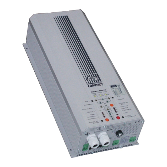
Please refer to the 'Display and Operating Panel' photograph on page 6
Sinewave Inverter, Battery Charger
Led 15
-
Led 16
-
Led 17
-
Led 18
-
Battery 75% - 100%
Battery 50% - 75%
Battery 25% - 50%
Battery 0% - 25%
- 9 -
