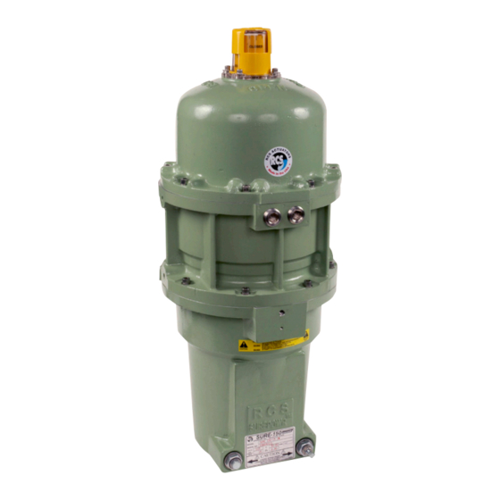
Dresser Surepowr Sure 150 Manuel d'installation - Page 11
Parcourez en ligne ou téléchargez le pdf Manuel d'installation pour {nom_de_la_catégorie} Dresser Surepowr Sure 150. Dresser Surepowr Sure 150 16 pages. Rcs actuators

Mechanical Stop Settings
NOTICE:
Only the fail end of travel stop may be adjusted.
The total adjustment available is +/- 5°.
To adjust the fail end position, perform the following:
• Use the adjustable, square, end of travel stop screw
to adjust the fail end of travel position (Figure 2).
• To make the end of travel stop adjustment, first loosen
the 3/8-inch lock nut to free the adjustment screw, then
turn the square adjustment screw.
• Be sure to re-tighten the lock nut in order to maintain
the enclosure rating.
NOTICE:
Do not loosen the large, 5/8-inch bolt in the
adjustment screw assembly. This will result in spring release
and will remove the spring pre-load.
NOTICE:
After adjusting the end stop, be sure to adjust the
actuator limit switches.
NOTICE: Do Not Adjust
Figure 5
Clock-Wise Spring Return Shown
(Counter Clock-Wise orientation will be seen as a mirror image)
Limit Switch Settings
NOTICE:
Do Not Adjust
For assembly/
disassembly only
Lock Nut –
release before
adjustment
of end stop
adjustment screw
End Stop Adjustment Screw
WARNING
EXPLOSION HAZARD
Death or serious injury
may result.
Switches must stop motor.
Switch 4
Switch 4
(auxiliary switch)
(auxiliary switch)
Switch 3
Switch 3
(auxiliary switch)
(auxiliary switch)
Switch 2 (Counter-CW
Switch 2 (Counter-CW
motor stop)
motor stop)
Switch 1 (Clockwise
Switch 1 (Clockwise
motor stop)
motor stop)
Cam Setscrews (1/16-inch hex drive)
Cam Setscrews (1/16-inch hex drive)
Figure 6
Switch adjustments for clockwise spring fail
operation (viewed from the top of the actuator)
Cam 1 actuates the clockwise motor stop switch.
Cam 2 actuates the counter-clockwise motor
stop switch.
Cams 3 and 4 are auxiliary switches.
To set the clockwise (spring fail position) switch:
a.
Ensure the actuator is positioned in the clockwise
(fail) position. Ensure the end of travel stop is
properly adjusted (see Mechanical Stop Setting
section). Loosen the setscrews on Cam 1 (1/16-inch
hex drive). Rotate Cam 1 counter-clockwise away
from its switch until it clears the switch lever.
b.
Rotate Cam 1 clockwise until it comes in contact with
its switch lever and the switch "breaks" (a light "click"
can be heard). Continue to rotate the cam slightly in
the clockwise direction; this ensures that the motor
will be switched off before the actuator reaches its
end of travel stop. Tighten the setscrews on Cam 1.
To set the counter-clockwise switch:
With the actuator in its full counter-clockwise position,
loosen set screws on Cam 2 so as to trip Switch 2 at
this position.
Auxiliary Switches:
Set Cams 3 and 4 to trip auxiliary switches as required for
the application.
Replace the cover and cover screws in accordance
with the specifications stated in the Installation
section of this manual.
Switch adjustments for counter-clockwise spring fail
operation (viewed from the top of the actuator)
Cam 1 actuates the clockwise motor stop switch.
Cam 2 actuates the counter-clockwise motor stop switch.
Cams 3 and 4 are auxiliary switches.
Cam 4
Cam 4
Cam 3
Cam 3
Cam 2
Cam 2
Cam 1
Cam 1
11
