Dresser Surepowr Sure 150 Manuel d'installation - Page 9
Parcourez en ligne ou téléchargez le pdf Manuel d'installation pour {nom_de_la_catégorie} Dresser Surepowr Sure 150. Dresser Surepowr Sure 150 16 pages. Rcs actuators
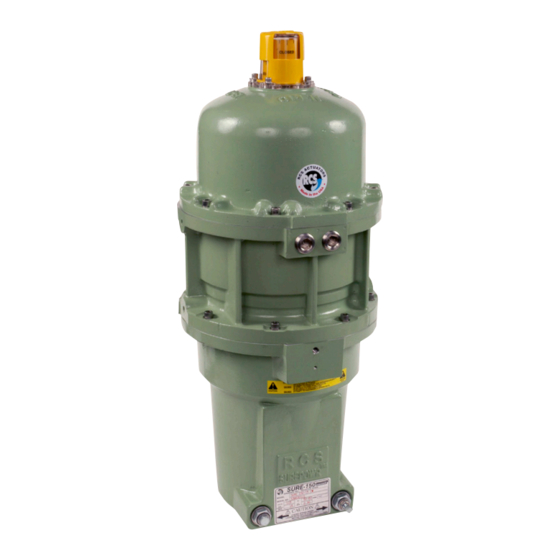
Conduit Locations and Thread Sizes
The actuator is supplied with two 2 3/4-inch NPT conduit
entries. Refer to Figure 1 (Sure 150 outline drawing) for
conduit entry locations.
Cable Glands
Ensure that the cable glands and wiring conform to
the applicable Explosion-Proof Equipment Standards
and to the Explosion-Proof Classification.
If an adapter is necessary to fit a cable gland, only one
adapter is allowed at cable entry.
If one of the cable entries is not used, it should be
sealed with a certified metal plug, without an adapter.
Cable glands should be fastened firmly to prevent
ingress of water or dirt and should be tightened to the
manufacturer's specified torque to ensure the required
enclosure protection.
Grounding and Bonding
The internal and external grounding points are
electrically connected within the actuator. The internal
grounding point is a green grounding screw located
on the surface of the top gear plate near the conduit
entry. The external grounding point location is shown
in Figure 4.
Location of External Grounding with Screw
Figure 4
Wiring
Connect field wiring per the appropriate wiring diagram
supplied with the actuator.
NOTICE:
Use a minimum of #18 AWG stranded wire.
Wiring Diagrams
Wiring diagrams vary according to specific product
configuration. Refer to the wiring diagram supplied
with the actuator.
NOTICE:
Units should be connected using the wiring diagram
supplied with the actuator.
NOTICE:
Direction of rotation is based on viewing the actuator from the top.
NOTICE:
To operate multiple actuators in parallel from a single source
requires isolating relays in the field wiring.
9