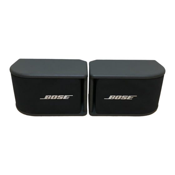
Bose 300PM Manuel d'entretien - Page 5
Parcourez en ligne ou téléchargez le pdf Manuel d'entretien pour {nom_de_la_catégorie} Bose 300PM. Bose 300PM 16 pages.
Également pour Bose 300PM : Manuel (13 pages)

DISASSEMBLY/ASSEMBLY PROCEDURES
Note: Refer to Figure 6 for the following
procedures.
1. Grille removal
1.1 Using your fingers, grasp the grille (1)
edge nearest the port slot and gently pull
the grille away from the cabinet until it
comes free.
1.2 Grasp the opposite edge of the grille
and gently pull it away from the cabinet
until it comes free as well.
2. Grille replacement
2.1 Orient the grille (1) so that the Bose
logo is aligned with the print on the rear of
the cabinet.
2.2 Align the two grille posts on the curved
grille edge with the cabinet grille socket
grommets (4) and press the grille edge in
place.
2.3 Align the two grille posts at the
opposite grille edge with the cabinet grille
socket grommets and press the grille in
place. The grille should be neat and flush
with the cabinet.
3. Driver removal
3.1 Remove the grille (1) using
procedure 1.
3.2 Using a phillips-head screwdriver,
remove the three screws (2) that secure the
driver (3) to the cabinet.
3.3 Using your fingers, grasp the plastic
basket of the driver and pull gently. The
driver should come free.
3.4 Note the driver wiring color code, and
cut the wires as close to the terminals as
possible.
4. Driver replacement
4.1 Observing polarity, solder the wires
from the crossover assembly (9) to the
driver (3) terminals.
4.2 Orient the driver correctly into the
cabinet and secure it using the screws (2)
removed in procedure 3.2.
4.3 Replace the grille (1) using
procedure 2.
5. Crossover Assembly removal
5.1 Remove the driver (3) located behind
®
the curved portion of the grille (1) using
procedure 3. Do not cut the wires to the
driver.
5.2 Remove the batting behind the driver
and retain it to reinstall later.
5.3 Using a long shaft phillips-head
screwdriver, remove the four screws (8)
that secure the crossover assembly (9) to
the binding post connector (10).
5.4 Gently pull the crossover assembly
straight off of the metal tabs on the binding
post connector until it comes free. You can
now slide the crossover assembly out
through the driver opening.
5.5 Unsolder the wires from the crossover
assembly.
6. Crossover Assembly replacement
6.1 Solder the driver (3) wires to the
appropriate locations on the crossover
assembly (9).
6.2 Insert the crossover assembly through
the driver opening.
6.3 Orient the crossover assembly so that
the tabs on the binding post connector (10)
and the receptacles on the crossover
assembly are aligned.
5
