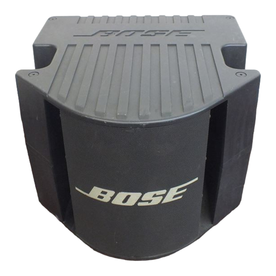
Bose ACOUSTIMASS PRO Manuel - Page 7
Parcourez en ligne ou téléchargez le pdf Manuel pour {nom_de_la_catégorie} Bose ACOUSTIMASS PRO. Bose ACOUSTIMASS PRO 19 pages.

General Test Setup
Caution!
There is no mains isolation
transformer in this amplifier! This amplifier
must be isolated from the AC line by a 1.0
kVa or larger isolation transformer during all
testing!
A stancore GIS-1000 or equivalent isolation
transformer should be used for 100VAC and
120VAC units.
A Siemens 4AX24-16-2BK or equivalent
isolation transformer should be used for
230VAC units.
A variac rated 1.0kVA or larger should be
used to vary the line voltage.
Output Loading: Unless otherwise speci-
fied, perform all tests with a series con-
nected 16Ω, 1%, 500 watt resistor and a
1.0mH, 10%, 5 amp rated inductor as the
load.
Input: Unless otherwise specified, apply a
1kHz, 1.0Vrms signal to the amplifiers
unbalanced input.
All output measurements should be made
with a 30kHz, 4 pole low pass filter in series
with the input of the measurement equip-
ment to reject the switching ripple.
1. Switching Frequency
1.1 With out an applied signal, measure the
switching frequency at the amplifier's out-
put. It should be 110kHz to 130kHz. Do not
use the 30kHz low pass filter when perform-
ing this test.
2. Output Ripple
2.1 The level of the switching frequency
should be less than 20Vpp. Do not use the
30kHz low pass filter when performing this
test.
TEST PROCEDURES
7
3. Voltage Limiting
3.1 Apply a 1.0Vrms, 100Hz signal to the
amplifier's input. Measure the output
according to the following table.
Variation
100V
120V
240V
4. Current Limiting
4.1 Apply a 1.0Vrms, 100Hz signal to the
amplifier's input and connect an 8Ω resis-
tive load to the output.
4.2 The output voltage should be 80.0Vp
± 8.0Vp (corresponding to 10A ± 1A).
5. Reference Gain
5.1 Apply a 50mV, 1kHz signal to the
amplifier's input. Reference a dB meter to
the applied signal.
5.2 Measure the output of the amplifier. It
should be 32.0dB ±1.5dB.
6. Frequency Response
6.1 Apply a 50mV, 1kHz signal to the
amplifier's input. Reference a dB meter to
the amplifiers output. Measure the output
according to the following table.
Note: Use the last six digits of the serial
number to determine which table to use.
The serial number is located on the side of
the amplifier as MK01xxx______ or
MZ01xxx______.
Output Voltage
Limit
104.5Vp to 115.5Vp
125.4Vp to 138.6Vp
125.4Vp to 138.6Vp
