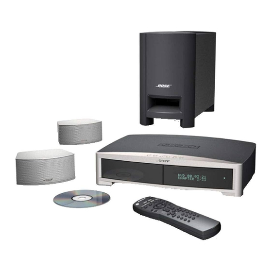
Bose 3-2-1 Manuel de dépannage - Page 6
Parcourez en ligne ou téléchargez le pdf Manuel de dépannage pour {nom_de_la_catégorie} Bose 3-2-1. Bose 3-2-1 28 pages. Home entertainment system
Également pour Bose 3-2-1 : Manuel du propriétaire (44 pages), Manuel d'installation rapide (1 pages)

1.4. Power Failure Detection
It is important to detect a power failure and alert the mircoprocessor to save any relevant infor-
mation and mute the power amplifiers so that no audio "pops" will be heard. The power failure
detection circuit (Q2, Q3, R11, R35, R40 and R15 [sheet 14, C7]) that we employ controls an
edge-triggered interrupt to the CS98200 microprocessor (U7003, pin 146 [sheet 5, C5]) to do
just that. If the voltage on V_UNREG falls below roughly 13.2V, the microprocessor will be
alerted that there is a power failure occuring. The interrupt will be unasserted (go high) when
V_UNREG goes above roughly 16.1V. This large hytsterisis is set so that dips in V_UNREG
caused by loud volumes will not inadvertantly trip a power fail interrupt. In a brownout condition,
the system will mute with the power dip and then recover gracefully when the normal line level is
restored (V_UNREG goes above 15.39V).
2. Processor and Its Peripherals
2.1 Processor
The CS98200 (U7003) from Cirrus Logic is the DVD decoder IC that functions as the console's
main processor. The CS98200 is a highly-integrated processor that provides all of the audio and
video processing functions needed for the next generation of feature-rich DVD players, DVD
receivers and Internet DVD applications such as MP3, Dolby Digital™, Dolby ProLogic II™, and
DTS Digital Surround™ decoding. It supports most popular CD formats, disk control, video
decoding and up to eight channels of audio output. The CS98200 also integrates six 10-bit
video digital-to-analog converters (DACs) and TV encoding with progressive scan functionality.
Progressive scan video provides high resolution and eliminates the "flickering" effect present in
traditional video playback.
The CS98200 contains two embedded 32-bit RISC processors, one of which is used as the
main processor in the 3
interfaces, with the exception of those offloaded to the ST micro on the Tuner Board. All of the
Main Board software runs on this processor. The second embedded CS98200 processor is
responsible for overseeing ATAPI, Memory and Host interfaces, DVD ROM Drive disc playback,
Hard Disk Drive store/playback and audio/video decode and generation. Software for this
processor is provided by Cirrus. An external FLASH and SDRAM are shared between the two
RISC processors.
2.1.1 Processor clock
Y7000 [sheet 2, B6] is the 27.0 MHz crystal for processor CS98200 (U7003) to derivate all
the internal system clock signals. C7001 and C7002 are the load capacitors. The crystal's
frequency accuracy should be within ±50ppm for color video operation.
2.1.2 Processor reset
U7002 [sheet 2, B6] generates a 140ms power-on pulse any time the +1.8V supply dips below
1.58 volts (including initial power-on). The pulse goes through RC network (R7015 and C7003)
to U7003's reset input pin 2. This same pulse also goes through another RC network (R7013
and C6219) to flash chip U6203's [sheet 6, C3] reset input pin 12. Those two RC networks have
a different time constant to ensure flash chip is out of reset before processor C98200.
THEORY OF OPERATION
•
•
2
1 Series II system. This processor controls all GPIO, sub-circuits and
6
