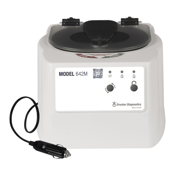
Drucker Diagnostics 642M Manuel d'entretien - Page 6
Parcourez en ligne ou téléchargez le pdf Manuel d'entretien pour {nom_de_la_catégorie} Drucker Diagnostics 642M. Drucker Diagnostics 642M 10 pages.
Également pour Drucker Diagnostics 642M : Manuel de l'opérateur (20 pages)

•
The centrifuge control panel is attached to the base internally with cable
harnesses. Be careful not to stress the cables when removing the cabinet.
•
Lift the cabinet straight up and off the base, setting it down on its front side.
•
Gently remove the combination power supply / motor harness from the control
board.
6.7. Replacing the Lid Lock Assembly
•
The lid locking tray assembly is accessible once the cabinet has been removed.
•
Gently remove the lid tray wire harness from the PCB.
•
The lid tray assembly is held in place with two #6 Nylok nuts. Use a 5/16" nut driver
to remove the nuts. The tray will slide off the threaded studs.
•
To install the lid tray, slide it onto the studs, and secure it with two #6 Nylok nuts,
hand tight.
•
Complete the installation by gently plugging the wire harness into the PCB header
'J1'.
6.8. Replacing the Control Board
•
The control board is part of the front panel assembly and is accessible once the
cabinet has been removed. Make certain that all wire harnesses have been
disconnected.
•
The control board has capacitors that will remain charged for a period after the
centrifuge is unplugged. Make certain to use standard precautions for handling
potentially charged capacitors when working with the control board.
•
The front panel assembly is held in place with ten locking tabs (fig 1).
•
Push the tabs inward to release the assembly.
•
To install the front panel assembly, push it into the opening in the cabinet until it
snaps into place.
DRUCKER DIAGNOSTICS
642M SERVICE MANUAL
Figure 1
SM023
REV C
6
