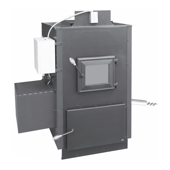
DS Stoves SF250 Manuel du propriétaire - Page 4
Parcourez en ligne ou téléchargez le pdf Manuel du propriétaire pour {nom_de_la_catégorie} DS Stoves SF250. DS Stoves SF250 17 pages. High efficiency auger fed rice coal furnace

Installation Instructions
1. Set on noncombustible level hard surface
prepared for 850 lbs
2. See Label or page 3 for clearance to
combustibles.
3. When installing screws, nuts, bolts and
pipes, it is always important to use an
anti-seize compound to aid in future
removal.
4. Assemble side ash slides (2 pcs part
#SF250-RLAS) to inside control side mounting plates
(part #'s SF250-ASMP & SF250-CSMP) using 4-¼ x ¾ (F) Black hex bolts and
4-¼" (J) Zinc nuts. Assemble back ash slide (part # SF250-BKAS) to the back
SF250-RLAS
SF250-RLAS
Fig. 2
SS hex bolts and 4-5/16 (I) SS nuts. See Fig. 3.
8. Attach snap disc conduit with 90
SF250-PTOP
SF250-9R
SF250-8R
SF250-7R
SF250-6R
SF250-5R
SF250-4R
SF250-3R
SF250-2R
SF250-1R
SF250-POT
Assembly
Seal Point
SF250-1AP
SF250-ASMP
snap disc conduit. See Fig. 3.
9. Assemble auger motor to auger motor mounting bracket (part #SF250-AMM) using 4-bolts & nuts
provided with auger motor. Install part #SF250-AMM to outside of part #SF250-CSMP using
2-5/16×3/4 (D) SS hex bolts and 2-5/16" (I) SS nut. See Fig. 3.
10. Insert standard auger pipe (part #SF250-1AP) into stoker pot inlet and tighten 2-5/16 x ¾ (D) SS
bolts. See Fig. 3.
Chart 1
baffle of stoker base. Using 2-¼ x ¾ (F) Black
hex bolts and 2- ¼" (J) Zinc nuts. Assemble front ash slide (part
#SF250-FTAS) to front panel of stoker base. Using 2- ¼ x ¾ (F)
Black hex bolt and 2- 1/4" (J) Zinc nuts. See Fig. 2.
5. Determine which side of furnace your coal hopper or coal bin will be.
Else right or left side. The coal hopper side is called the auger side
of furnace in this manual. The side opposite the coal hopper is
called the control side of furnace
6. Install (part #SF250-ASMP) to auger side of furnace. Using 8 -
5/16×3/4 (D) SS hex bolts and 8-5/16" (I) SS nuts. See Fig. 3.
7. Assemble pot assembly (part #SF250 pot-assem) to inside of
control side mounting plate (part #SF250-CSMP) using 4-5/16×3/4 (D)
connector to #SF250-CSMP and insert snap disc wiring through
o
A
x4
Fig. 3 NOTE: When assembling pot do not over tighten
Pot Rings. Make sure they are centered or your pot fire
will not be centered.
SF250-PI
C
x4
SF250-PCO
A - 3/8" x 7 1 /2"
B - Auger Motor Bolt
and hardware
(supplied with auger)
C - 3/8" x 3/4" SS hex bolt
D - 5/16" x 3/4" SS hex bolt
E - 1/4" x 1" SS hex bolt
F - 1/4" x 3/4" Black hex bolt
SF250-CSMP
F
D
x2
x4
SF250-RLAS
Snap Disc
(right & left)
Wiring
SF250-FTAS (front)
SF250-BKAS (back)
4
H - 3/8" SS nut
I - 5/16" SS nut
J - 1/4" Zinc nut
K - #14 x 3/4" Black head
self-tapping screw
L - #8 x 3/4" Black head
self-tapping screw
M - Shear Pin SF250-SPIN 1/8
HR round 2" long with
0.04 x 0.8 hairpin
M
Shear Pin
SF250-AMM
Auger Motor
D
x2
E
x4
Combustion
Blower
Fig. 3
Snap Disc
Conduit
