DS Stoves SF250 Manuel du propriétaire - Page 5
Parcourez en ligne ou téléchargez le pdf Manuel du propriétaire pour {nom_de_la_catégorie} DS Stoves SF250. DS Stoves SF250 17 pages. High efficiency auger fed rice coal furnace

Installation Instructions
11. Disassemble Pot Ring #SF250-PTOP from pot assembly. Install part #SF250-CSMP on control
side of furnace using 8-5/16 x ¾ (D) SS Hex bolts and 8-5/16" (I) SS nuts. Insert short auger pipe
through inside of stoker furnace and out the 2-7/16" hole of part #SF250-ASMP. See Fig. 3.
Reassemble Pot Ring #SF250-PTOP to pot assembly. See Fig. 3 Note.
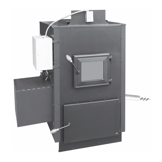
12. Install electrical control box on the control side of furnace using 2-#14 x ¾ (K) self tapping screws.
See Fig. 4
Bend out 2 tabs for motor
cover shield to slide into.
Motor Cover Box
optional right or
left side
13. Remove pot insert part #SF250-PI from bottom of pot see Fig. 3, page 4. Insert main auger
through short auger pipe on auger side of furnace and attach to auger motor on control side of
furnace using shear pin (M). See page 5, Fig. 3. Re-install pot insert. Note: You must remove pot
insert from pot bottom to install or remove short auger.
14. Seal all joints where auger pipe exits furnace, and where pipe coupler is used for 5' and 8' auger
extension option, seal both ends of pipe coupler as well as where you enter your hopper or bin.
Use #641 Seal-It-Right caulk. Provided with furnace. See Figs. 3, 14, 15, 16.
15. Install limit switch on top plenum of furnace by hot air duct work outlet see Fig. 4. See page 6 for
limit switch wiring diagram.
16. Assemble motor cover box using #8 - 1/2" screws provided with unit. You must bend out the tabs
on the control side of furnace for the motor cover box tabs to slide into. See Fig. 4.
17. Assemble filter box for back of unit. Following instructions with filter box. You can assemble filter
box to have filter on right or left side of furnace. Do not install top of filter box until filter box is
screwed to back of unit. Screw filter box to back of unit, do not completely tighten the 2 top screws
because you need room to slide the top of filter box in behind these screws. Install blower on back
of unit, connect conduit from electrical box to hole in the top of filter box. Connect the 5 wires in
conduit to the 5 wires on blower using the 5 wire nuts in hardware bag provided with the furnace,
connect white wire to purple wire, green wire to green wire, red wire to red wire, blue wire to yellow
wire and black wire to black wire. Install top of filter box and tighten top 2 screws on back
accessing thru filter box opening. Install 20" x 20" pleated filter.
18. Install a barometric damper in your chimney system. With furnace operating at normal temperature
adjust barometric damper so that you have about a negative .05 or negative .06 inches of water
column in your single wall chimney connector approx. 12" below barometric damper.
See page 3, Fig. 1.
19. Have a licensed electrician connect all your wiring. Make sure all power is disconnected from
furnace before opening control box. Connect limit switch and snap disc wiring to control box as
shown in wiring diagram. See Fig. 5.
20. Hook up return duct to return box at back of unit.
21. Install thermostat and hook up thermostat wire to thermostat wire connectors on control box.
Control Box optional
right or left side
5
Fig. 4
Limit Switch
located on
front duct work
panel
