Concoa 529 5310 Manuel d'installation et d'utilisation - Page 2
Parcourez en ligne ou téléchargez le pdf Manuel d'installation et d'utilisation pour {nom_de_la_catégorie} Concoa 529 5310. Concoa 529 5310 17 pages. Multi-station remote alarm

PART NUMBERS
529 5310
529 5311
DESCRIPTION OF PRODUCT
The Multi-Station Remote Alarm is set at the factory to operate at either 120VAC or 220VAC. It is capable of
providing operating status for up to four CONCOA Autoswitch systems. The Multi-Station Remote Alarm provides
power to each Autoswitch to operate the status indicator lights and the pressure switches.
An Autoswitch product that is configured with the alarm option is equipped with two pressure switch gauges, two
sets of status indicators, and a power status indicator. A pressure switch gauge and one set of status indicators are
used to monitor and report the state of the pressure for each side of the Autoswitch.
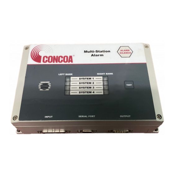
The front panel of the Remote Alarm consists of eight (8) status indicator lights, an "Alarm Silence" button, a "Test"
button, and an audible Alarm. See Figure 1. In addition to the front panel, the right side of the Remote Alarm has
a power ON-OFF switch and an IEC type connector where the AC power cable is connected. At the bottom of the
Alarm are three (3) connectors where the Autoswitch, Serial Port and Output Devices are connected.
The Multi-Station Remote Alarm controls five (5) sets of relay contacts that are brought to the Output Connector
so they may be used to control an external device.
The status indicator lights are organized into pairs representing the Left Bank and Right Bank of an Autoswitch
System. When all configured systems are operating normally the status indicator lights will be green. If the pressure
should drop below the preset value of the Autoswitch, the audible alarm will sound and the light corresponding to
the specific Autoswitch Bank will turn from green to red. When this happens, two output relays will activate; the
MAIN relay and the AUX relay connected to the system that had the alarm condition. The MAIN Relay will
always activate whenever any of the AUX relays activates. It is sometimes desirable to silence the audible alarm
prior to the alarm condition being fixed. Pressing the "Alarm Silence" button will accomplish this. The status
indicator lights and the relays will remain activated until the alarm condition is corrected. If the second bank
on the same Autoswitch generates an alarm while the first Bank is still in an alarm condition, the other status
indicator light in that system will turn from green to red, however, both red status indicator lights on that system
will start to blink ON and OFF. If the audible alarm was previously silenced, it will sound again.
Audible Alarm
Input Connector
Multi-Station Remote Alarm 120 VAC version
Multi-Station Remote Alarm 220 VAC version
Serial Port
Output Connector
Figure 1
Status Indicator Lights
Alarm Silence Switch
-2-
Test Switch
Power Switch
Power Connector
