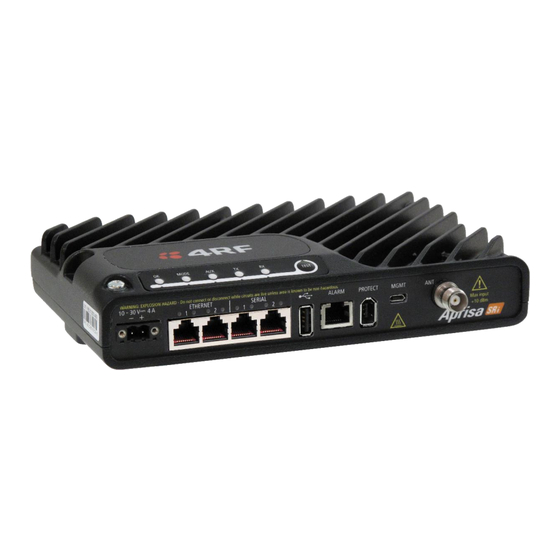
4RF Aprisa SRi Manuel de démarrage rapide - Page 9
Parcourez en ligne ou téléchargez le pdf Manuel de démarrage rapide pour {nom_de_la_catégorie} 4RF Aprisa SRi. 4RF Aprisa SRi 12 pages.

Page 9
Monitoring and Troubleshooting the Aprisa SRi Radio
4.
4.1. Monitor the Aprisa SRi Radio Signal Strength
When the network is installed, the radio signal strength can be monitored on remote
stations by setting the radio to Test Mode.
To enter Test Mode, press and hold the TEST button on the radio LED panel until all
the LEDs flash green (about 3 - 5 seconds).
In Test Mode, the LED Display panel presents a real time visual display of the RSSI.
This can be used to adjust the antenna for optimum signal strength.
Note: The response time is variable and can be up to 5 seconds.
To exit Test Mode, press and hold the TEST button until all the LEDs flash red (about
3 – 5 seconds).
The OK, MODE and AUX LEDs will be solid green and the TX and RX LEDs will be solid
or flash green if the network is operating correctly.
The RSSI result is displayed on the LED display panel as a combination of LED states.
For more information, please refer to the Aprisa SRi User Manual available from the 4RF website
https://www.4rf.com/secure
(login required).
4.2. Fault Management and Troubleshooting
The Aprisa SRi support extensive alarms for every section and building block of the device including the interfaces. SuperVisor
allows user to view the main summary alarm at the top of the SuperVisor page which mimic the device LEDs and in addition all
the detailed alarms of the device (see SuperVisor > Events > Alarm Summary). In addition, SuperVisor allows user to troubleshoot
any alarm issue by using the event history log page for more information about the alarm (see SuperVisor > Events > Event
History). For more information see the Aprisa SRi user manual.
