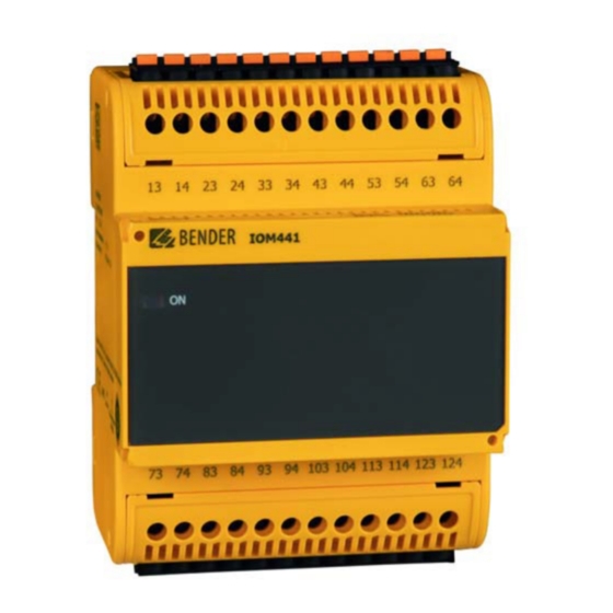
Bender B95012057 Manuel - Page 5
Parcourez en ligne ou téléchargez le pdf Manuel pour {nom_de_la_catégorie} Bender B95012057. Bender B95012057 8 pages. Relay module
Également pour Bender B95012057 : Manuel (8 pages)

3. Befestigungslöcher für M4-Gewinde gemäß dem Maß-
bild bohren.
4. Geräte mit jeweils zwei M4-Schrauben befestigen.
Montage auf Hutschiene
1. Montageclips gemäß Abbildung anbringen
2. BB-Bus am Gerät anbringen. Die BB-Bus Montageanlei-
tung beachten.
3. Das IOM441-S mit Abstand neben dem Grundgerät auf
der Hutschiene einrasten.
4. Beide Geräte zusammenschieben, so dass die Kontakte
des BB-Busses miteinander verbunden sind.
Sachschäden durch unsachgemäße Demon-
tage
Wird eines der beiden verbundenen Geräte
VORSICHT
demontiert ohne die Verbindung durch seit-
liches Verschieben zu trennen, drohen Sach-
schäden an dem BB-Bus und den damit ver-
bundenen Geräten. Geräte immer erst durch
seitliches Verschieben trennen.
Anschluss
Verdrahten Sie das Gerät gemäß Anschlussplan.
Beachten Sie dabei die technischen Daten. Montieren
Sie nach dem Anschluss die mitgelieferten Klemmen-
abdeckungen!
Inbetriebnahme
Das Grundgerät versorgt das IOM441-S über den BB-
Bus. Versorgungsspannung des Grundgerätes einschal-
ten.
Die Parametrierung erfolgt über das Grundgerät.
IOM441-S_D00300_02_M_DEEN / 02.2019
DIN rail mounting
Connection
Grundgerät
Basic device
Wire up the device according to the wiring diagram..
Please observe the technical data. After connecting the
device, install the enclosed terminal covers!
Commissioning
Switch on the supply voltage of the basic device. The
basic device supplies the IOM441-S via the BB bus.
Parameter setting is carried out via the basic device.
3. Drill the mounting holes for the M4 thread according to
the dimension diagram.
4. Fix the devices with two M4 screws.
1. Fix mounting clip shown on page 4.
2. Attach the BB bus to the device. Please observe the
mounting instructions provided with the BB bus
3. Snap the IOM441-S on the DIN rail at some distance to
the basic device.
4. Slide the devices towards each other until their BB bus
connectors have been interfaced.
Risk of damage to property due to incorrect
disassembly
If one of the two connected devices is dis-
CAUTION
assembled without separating the connec-
tion by sliding them to one side, the BB bus or
the connected devices may be damaged.
Slide the devices to one side in order to
separate the connection.
Ausgänge Relais
Outputs Relays
IOM441-S
IOM441-S
Ausgänge Relais
Outputs Relays
IOM441-S / IOM441W-S
5
