ADENDORFF MCll00 Manuel d'instruction - Page 10
Parcourez en ligne ou téléchargez le pdf Manuel d'instruction pour {nom_de_la_catégorie} ADENDORFF MCll00. ADENDORFF MCll00 18 pages. Variable speed wood lathe

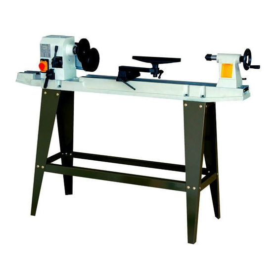
Erecting the leg set (Figure 2)
1. Attach one front and one back leg [1] to the
outside edge of the top plate [2] using
carriage bolts [3], washers [4], and nuts [SJ.
2. Posrtion the top plate so that it fits inside the legs.
3. Repeat step 1 for the opposite side.
4. Attach long supports [6] to legs us:ng
carriage bolts, washers and nuts.
5. Attach short supports [7] to legs using
carriage bolts, washers, and nuts.
6. Place the stand on a level surface and tighten
all nuts securely using a 14 mm wrench or
adjustable wrench.
Setting the lathe on the leg set (Figure 3)
1. Place the lathe bed assembly (1] on the leg set.
2. Position the headstock [2] assembly over the
top plate and align the holes in the bed [3]
with the holes jn the top plate [4]. Set the
headstock down carefully.
3. Align the tailsto:ck assembly end of the lathe
over the .top plate mounting holes and set it
down carefully.
4. Insert the hex bolts [5] into the mounting
holes in each bed and into the top plate.
5. Thread washer [6] and nut [7] onto bolt [5].
and tighten securely.
IMPORTANT:
THE LEG SET MUST BE FASTENED TO THE SUPPORTING SURFACE.
Head lock handle (Figure 4)
1. Locate and assemble the head locking
handle [1 ], spring [2] and bolt [3] as shown.
2. Thread assembled handle into the head
locking clamp [4] and tighten.
NOTE:
Spring loaded handles
The spring loaded handles on the lathe
are designed to minimize interference with other
Jathe parts or the workpiece.To operate,
push the handle lever in and tum clockwise to
tighten. Releasing the handle lever will
disengage the threaded shaft, allowing you to
reposition the lever handle so it is out of the way.
VI • Assembly
Fi g . 2
4
6
2-----1 1
Fi g . 3
0
0
..
•
1
4
0
7
Fig. 4
