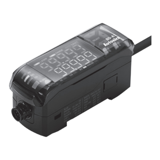
Autonics BD Series Manuel - Page 11
Parcourez en ligne ou téléchargez le pdf Manuel pour {nom_de_la_catégorie} Autonics BD Series. Autonics BD Series 14 pages. Laser displacement sensors amplifier unit
Également pour Autonics BD Series : Manuel du produit (6 pages), Manuel du produit (5 pages), Manuel du produit (3 pages)

BD Series
▣ Parameter Group
• Push the [MODE] key over 2 sec to enter the parameter setting mode.
• In the setting mode, change the parameter group by the [◀/▶] keys and enter the group by pushing the [MODE] key.
• In the group, change the parameter by the [◀/▶] keys, select it by pushing the [MODE] key, and change the setting value by [▲/▼] keys
• In the each step, push the [MODE] key over 3 sec to save and return to the upper step.
※Some parameters are enable by related parameter setting.
Parameter group 1
Settings related to output type, displacement,
PARA1
display and error output.
Parameter
Setting range
Response
330㎲, 500㎲, 1ms, 2ms, 5ms
time
RSPD
Teaching
mode
SENS
NoNC Output type
DISP PV display
SCALE
Display
0.000, 0.00, 0.0, 0
digit
DOT
H-SC Display
-99.999 to 99.999
scale
L-SC
HYS Hysteresis
0.001 to 99.999
H-AN Analog
output
-99.999 to 99.999
scale
L-AN
Error
output
ERrOUT
Fixed
Set analog output range
output
FIxOUT
Parameter group 2
Settings related to present value.
PARA2
Parameter
Setting range
CALC Calculation
ADD-AB
SUB-AB
GAIN Gain
1, 2, 3
FILTER Filter
Samples for
1, 2, 4, 8, 16, 32, 64, 128, 256,
averaging
512, 1024, 2048, 4096
AVF
Samples for
OFF, 3, 5, 7, 15, 31
median
MEDIAN
HOLD Hold
BOTTOM
SAMPLE
Hold timing
input
HOLdT
Auto trigger
-99.999 to 99.999
level
AtLV
Auto trigger
0.001 to 99.999
hysteresis
AtHYS
T-MOD Timer
TIME Timer value 0 to 9999
E-16
Default
1-point
1PNT
2-point
2PNT
Normally open
NO
Normally closed
NC
Standard
STND
Scale
by models
by models
Keep PV
KEEP
Fixed value
FIX
Default
Off
OFF
Add
Subtraction
Average mode
AVG
Average filter
AVF
Differential filter
DIFF
Off
OFF
Peak
PEAK
Bottom
Difference
P-P
Sample
Average
AVG
External input
T-IN
Over auto trigger
AtUP
level
Under auto trigger
AtDW
level
Off
OFF
Output delay
OND
Output hold
OFD
Parameter group 3
Settings related to external input.
PARA3
Parameter
External
input 1
1ms
D-IN1
External
input 2
D-IN2
1PNT
External
input 3
D-IN3
NO
External
input 4
STND
D-IN4
0.000
Parameter group 4
Settings related to user convenience functions.
Different
PARA4
Parameter
Display
0.001
direction
DIR
Different
BANK Bank
Saving
mode
SAVE
KEEP
Max.
value
LOCK Lock mode
INIT Initialize
OFF
※Parameter group 4 is common, not saved per bank separately.
1
AVF
16
OFF
OFF
T-IN
0
0.001
OFF
0
Setting range
Off
OFF
Timing input
T-IN
Output reset
OUtCLR
Stop emission
L-OFF
Zero adjustment
ZERO
Bank input-A
BANK-A
Bank input-B
BANK-B
Setting range
[▲/▼] (select direction)
→ [MODE] (apply)
BANK-0,,BANK-1
BANK-2,,BANK-3
Off
OFF
Digital display
SAVE1
All display
SAVE2
Off
OFF
[AUTO], [ZERO]
LOCK1
[AUTO], [ZERO]
LOCK2
+ entering parameter
group
All key
LOCK3
(except unlock key)
OFF, CLR-B0, CLR-B1,
CLR-B2, CLR-B3, CLR-A
Default
T-IN
OUtCLR
L-OFF
ZERO
Default
Normal
display
BANK-0
OFF
OFF
OFF
