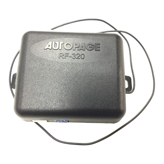
Autopage RF-320 Manuel d'installation - Page 4
Parcourez en ligne ou téléchargez le pdf Manuel d'installation pour {nom_de_la_catégorie} Autopage RF-320. Autopage RF-320 12 pages. Professional vehicle security system

H3: 8-PIN MINI CONNECTOR WIRE HARNESS.
H3/1. BROWN/ WHITE WIRE -- (-) HORN OUTPUT --
This wire i s provided to use the existing vehicle's horn as the alarm system's optional
warning audible device. It's a transistorized low current output, and should only be
connected to the low current negative (-) output from the vehicle's horn switch.
Connection should be made at steering column near horn switch.
H3/2. WHITE WIRE – (-) 200mA DOME LIGHT CONTROL OUTPUT –
rd
(Optional 3
output see programming feature A -5)
This wire becomes grounded when the dome light controls circuit active. The current
capacity of this wire is 200mA. This wire can control the operation of the interior lights.
An optional 10 Amps relay can be used to this system for interior lights operation.
a). Upon disarming, the interior lights will remain on for 30 seconds.
b). If the vehicle is v iolated, the interior light will flash for the same duration as the siren.
H3/3. VIOLET WIRE -- POSITIVE DOOR SWITCH SENSING INPUT--
This wire is the positive trigger input wire for positive door pin switch. This wire
connection is for "positive" type factory door pins(typical FORD MOTOR). Locate the
"common wire" for all door pin switches and make the connection of the Violet Wire.
H3/4. BLUE WIRE -- GROUND INSTANT TRIGGER INPUT --
This wire is the ground trigger input wire for hood/trunk pin switches.
H3/5. GREEN WIRE -- NEGATIVE DOOR SWITCH SENSING INPUT --
This wire is the ground trigger input wire for negative door pin switch. This wire
connection is for "grounding" a factory-type door pin switch; locate the "common wire"
for all door pin switches and make the connection of the Green Wire.
H3/6. YELLOW WIRE – TO IGNITION SWITCHED +12V --
This wire is connected to a Ignition switched 12 volts source. This wire should receive
"12 Volts" when the ignition key is in the "ON" and "START" position. When the ignition is
turned "OFF", this wire should receive "0" voltage.
H3/7. ORANGE WIRE – (-) 200mA GROUNDED OUTPUT WHEN ARMED --
This wire will become grounded when the alarm is armed. The current capacity of this
wire is 200mA. This output can control starter disable, when an intrusion is detected and
the system is triggered. The alarm will prevent any unauthorized persons from starting
the vehicle. NOTE: If more than one electronic device will be connected to the H3/5
ORANGE Wire, it will be necessary to isolate the connection of each device control
wires with a 1N4003 diode. ( relay required, Optional )
<12V (+) Ignition>
<Starter Wire (key side)>
<Starter Wire (motor side)>
STARTER
RK-1
87
<Red>
87a
85
86
<Yellow>
30
<Purple>
4
Orange
<White Wire>
Starter Disable
Wire
