Galvanic Isolator Gi-120/A Manuel d'instructions - Page 3
Parcourez en ligne ou téléchargez le pdf Manuel d'instructions pour {nom_de_la_catégorie} Galvanic Isolator Gi-120/A. Galvanic Isolator Gi-120/A 7 pages.

Installation - Fixing the Isolator continued
As a further measure to prevent water ingress, when fixed, apply a little sealant to the heads of the fixing
screws.
If the lid has been disconnected, re-connect the terminals, ensuring that
they are pushed fully home.
Re-fix the isolator lid. The screws should be tightened firmly, taking care
not to overtighten.
Installation - Connecting the Isolator
Switch off the electricity supply at the shore supply, and disconnect
the shore line.
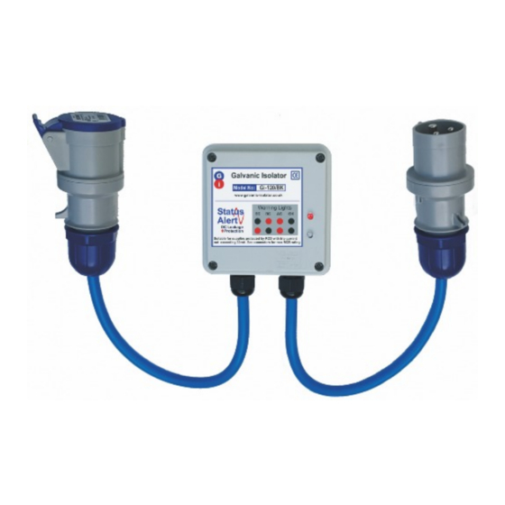
Connect the isolator to the chosen end of the shore line.
Connect the free end of the isolator to the boat or shore connector.
Switch on the electricity supply at the shore supply.
Check that the RCD test button on the boat operates normally
You are now protected.
Note:
Isolators may be supplied with the connectors either way around. If you wish to
change them this is permissible. Simply interchange the connectors, paying
attention to polarity. Please ensure connecting screws and gland nuts are tight.
To open the connectors, please press clip (see photo), and twist connector
body halves in opposite directions.
If in doubt, please seek advice from a qualified person.
IMPORTANT:
To prevent water ingress, before installation, and
periodically, check Gland
Nuts on both cable ends for
tightness (Blue in photo).
Gland Nuts should be as tight
as possible USING HAND
FORCE ONLY.
