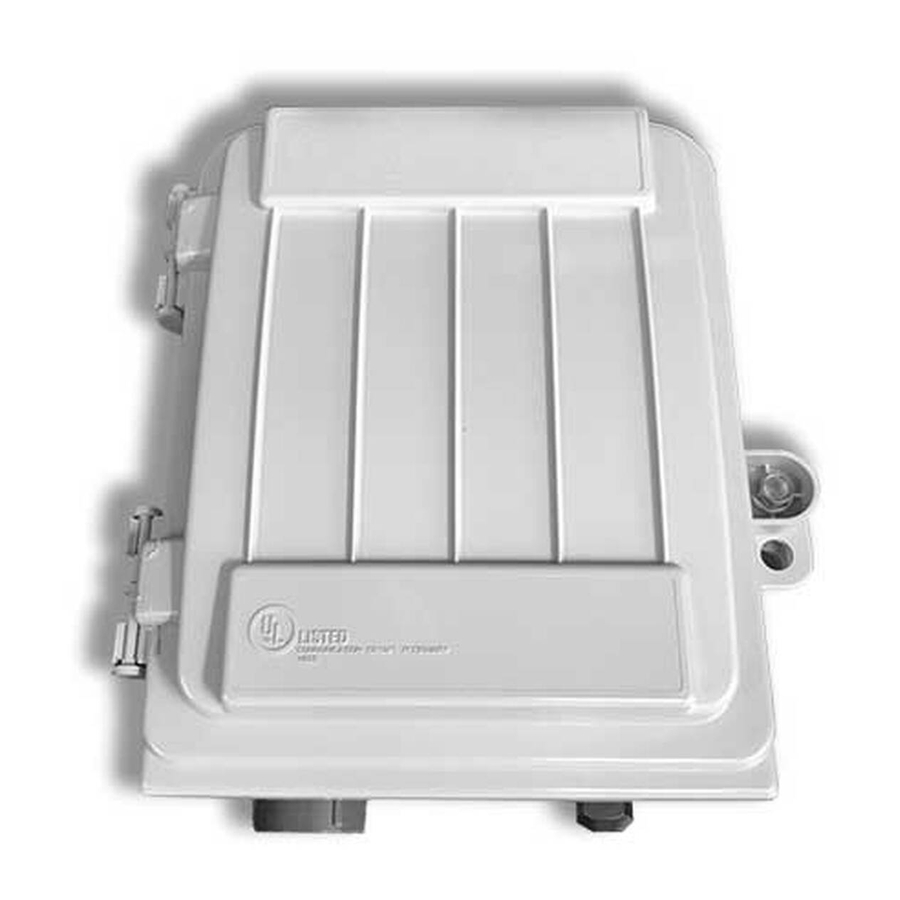
AFL OptiNID 500 Manuel d'instructions d'installation - Page 5
Parcourez en ligne ou téléchargez le pdf Manuel d'instructions d'installation pour {nom_de_la_catégorie} AFL OptiNID 500. AFL OptiNID 500 8 pages. Optical demarcation closure

CABLE INSTALLATION
6. Place one wrap of a foam spacer around
the buffer tube.
7.
Secure the buffer tube to the splice tray using
a tie wrap. (Figure 3)
PIGTAIL
INSTALLATION
Caution: In order to avoid micro bends or fiber
damage do not over-tighten the tie wraps around
the fiber bundles.
1. Use accepted local practice to clean the connector
end face.
2. Plug the pigtail assembly into the adapter plate as
specified by the local engineering practice.
3. Repeat steps 1-2 for each additional pigtail assembly
to be installed.
4. Route the pigtail assemblies to the splice tray.
Note: For best practice it is recommended that the
pigtail assemblies be routed through protective
transport tubing for mounting into the splice tray.
5. Place one wrap of a foam spacer around the tubing
6. Secure the tubing to the splice tray using a tie wrap.
(Figure 4)
COMPRESSION
FITTING INSTALLATION
Caution: In order to avoid micro bends or fiber
damage do not over-tighten the tie wraps around
the fiber bundles.
INSTALLATION INSTRUCTIONS
(CONTINUED)
5
OptiNID
500 Optical Demarcation Closure
®
Figure 3
Figure 4
© 2017, AFL, all rights reserved. Revision A, 2.16.2017
Specifications are subject to change without notice.
