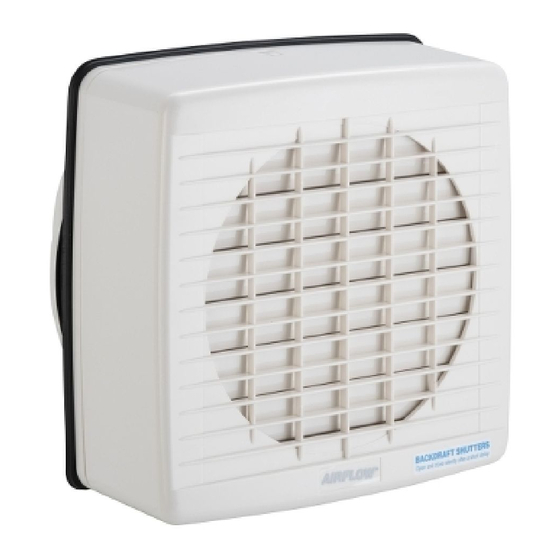
Airflow 7005A Instructions d'installation - Page 2
Parcourez en ligne ou téléchargez le pdf Instructions d'installation pour {nom_de_la_catégorie} Airflow 7005A. Airflow 7005A 2 pages. Maxair window exhaust fans

7005A & 7007A
1.
"A" Internal clamp
sub-assembly
2.
• Make sure the external seal is against the
glass, align and insert the bolts.
• Brass nuts supplied should be connected
and finger tightened only.
3.
Apply soap to
the foam seal
Fan assembly
MaxAir Window Exhaust Fan Installation Instructions
• Cut hole in glass 212mm Ø ± 2.0mm.
• Locate internal clamp sub-assembly
"A", slide over your arm as shown.
• Locate external clamp sub-assembly
"B", fold and insert through the hole in the
window pane.
"B" External clamp
sub-assembly
Finger
tighten
only
• If required, apply liquid or similar soap
to foam seal on inside of external clamp
sub-assembly.
• Carefully slide cylindrical window
grille outlet end of fan assembly
through opening.
• With screws provided, attach fan assembly
to window clamp assembly (four places).
© Clipsal Australia Pty Ltd
7005A & 7007A
4.
Screws labelled 1, 2, 3 retain the
terminal cover to the chassis
5.
• Place cover assembly as shown.
• Tighten retaining screw.
• Test. Ready to go.
• This appliance is not intended
for use by children or infirm
persons without supervision.
• Children should be supervised
to ensure they do not play with
the appliance.
• Fan should be mounted 2.3m
above the floor.
• Appliance intended for exterior
window mounting only.
© Clipsal Australia Pty Ltd
MaxAir Window Exhaust Fan Installation Instructions
Break tab for
cable access
• Remove termination cover (screws
labelled with 1, 2, 3). Electrician to make
electrical connection. (3 core flex,
7mm Ø [17/64"] specified).
• Stripped ends to be kept to a minimum.
• Cable (3 core flex) to be placed as shown
below in wiring diagram.
• Replace termination cover.
Retaining
screw
