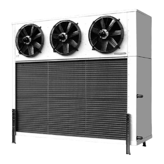
FRIMETAL MRB-1050 Manuel d'instruction - Page 8
Parcourez en ligne ou téléchargez le pdf Manuel d'instruction pour {nom_de_la_catégorie} FRIMETAL MRB-1050. FRIMETAL MRB-1050 16 pages.

Evaporadores con motores Ø 710
Estos ventiladores son del tipo tubular de alta presión preparados para
trabajar a dos tensiones según conexión: estrella (
gulo (
) a 400V, viniendo de fábrica conectados a 400V. Llevan la caja
de conexiones detrás de la hélice y para acceder a ella debe quitarse
previamente la rejilla del ventilador.
Se adjuntan los dibujos con las conexiones en las cajas de los ventila-
dores con los siguientes elementos:
5 Regleta de conexión de seis terminales.
6 Manguera con los cables que salen del motor.
7 Manguera con 4 cables que sale hacia la caja de conexiones exte-
rior. Estos cables corresponden a las tres fases de línea L1, L2 y L3
y a la conexión a tierra PE.
8 Puentes que se pueden cambiar para tener conexión
(400V estándar de fábrica)
Este esquema de conexiones viene también en una pegatina colocada
en el interior de la tapa de la caja de conexiones de cada ventilador.
2-CAJA DE CONEXIONES EXTERIOR
La conexión eléctrica debe realizarse directamente en la caja de cone-
xiones situada en el lado opuesto a las conexiones frigoríficas y se
accede a ella quitando la tapa lateral superior del evaporador. A esta
caja llegan las mangueras de 6 cables de cada ventilador (para venti-
ladores de Ø500 y 630) o 4 cables de cada ventilador (para ventilado-
res de Ø710) que van conectadas a los terminales independientemen-
te.
1 Diagrama de conexión para modelos con uno o dos ventiladores.
2 Diagrama de conexión para modelos de tres o cuatro ventiladores.
8
Units with Ø 710 fan motors
These are tubular aerofoil fans of high pressure and air flow. They have
) a 690V y trián-
two tensions according to the connection: 400V triangle
and 690V with star
400V connection. The junction box is stuck to the motor behind the fan
blades and it is necessary to remove the fan motor grille to access to it.
Below there are the drawings with the connections inside the junction
box on the fan motor that includes the following parts:
5 Terminal strip with 6 connections
6 Hose with the wires coming from the motor
7 Hose with 4 wires coming out to the external junction box. These
wires correspond to the three-phase line L1, L2 and L3 and the
ground connection wire PE.
(690V) y
8 Removable bridge-wires to change from connectin
tory standard) to
The fan motor connection drawing is also displayed in a label stuck on
the inner side of each junction box lid.
2-EXTERNAL JUNCTION BOX
The electric wiring must be done directly in the junction box placed on
the side of the evaporator opposite to where the refrigerant connec-
tions are situated. This box is accessible removing the upper lateral
plate from the evaporator. To this box arrive the hoses coming from the
fan motors with 6 wires each (500 and 630mm fan motors) or 4 wires
(710mm fan motors), which are connected to the terminal strips inde-
pendently.
1 Connection diagram for models with one or two fan motors.
2 Connection diagram for models with three or four fan motor.
connection. They are delivered ex-works with
(690V).
connection
(400V fac-
