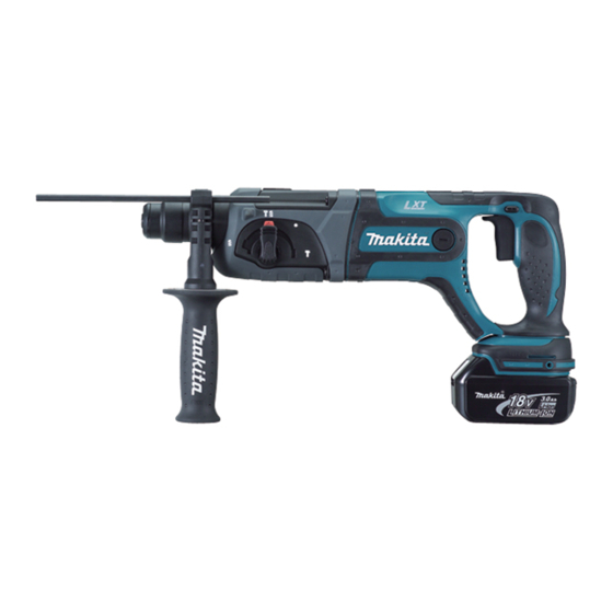
Makita BHR241 Informations techniques - Page 8
Parcourez en ligne ou téléchargez le pdf Informations techniques pour {nom_de_la_catégorie} Makita BHR241. Makita BHR241 14 pages. Cordless combination hammer
Également pour Makita BHR241 : Informations techniques (14 pages)

R
epair
[3] DISASSEMBLY/ASSEMBLY
[3] -7. Impact Bolt Section (cont.)
ASSEMBLING
2) Push Ring spring 28 with Piston cylinder until it fits to the inner groove of Tool holder complete. (Fig. 29)
Fig. 29
Note: Use an extra Piston cylinder as a jig. Never use Piston cylinder that is to be
assembled to the machine.
Piston cylinder
as a repairing jig
Ring spring 28
Tool holder
complete
[3] -8. Swash Bearing Section
DISASSEMBLING
1) Disassemble Tool holder section as illustrated in Fig. 3.
2) Disassemble Change lever as illustrated in Figs. 4 and 5.
3) Separate Gear housing complete from Motor housing complete. And then, remove Armature from Gear housing complete.
(Refer to Figs. 8 to 10.)
4) Remove Stop ring E-4, Flat washer 5 and Compression spring 6 from pin of Inner housing complete. (Fig. 30)
5) Remove two M4x12 Hex socket bolts that fasten Bearing retainer to Inner housing complete. (Fig. 31)
Fig. 30
Pin of Inner housing complete
Stop ring E-4
Flat washer 5
Compression spring 6
Change plate
Piston cylinder
as a repairing jig
Inner groove of
Tool holder complete
Ring spring 28
O ring case
Fig. 31
M4x12 Hex socket
head bolt (2 pcs.)
See more at http://safe-manuals.com
P 8/ 14
