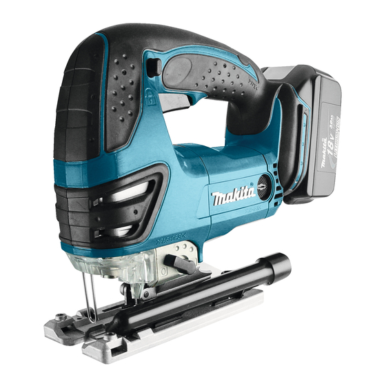
Makita BJV180 Informations techniques - Page 13
Parcourez en ligne ou téléchargez le pdf Informations techniques pour {nom_de_la_catégorie} Makita BJV180. Makita BJV180 13 pages. Cordless jig saw
Également pour Makita BJV180 : Ventilation des pièces (3 pages), Fiche technique (2 pages), Manuel d'instruction (13 pages), Manuel d'instruction (13 pages), Manuel d'instruction (13 pages), Manuel d'instruction (18 pages)

W
iring diagram
Wiring in Handle (L)
Route Lead wires as illustrated in Fig. 43.
1 Lead wires of Endbell (black):
Route between the rib and the boss, and connect to No.M1 terminal of Switch.
Note: Be sure to fix with Lead wire holder A.
2 Lead wires of Endbell (red):
Route between the rib and the boss, and connect to No.M2 terminal of Switch.
Note: Be sure to fix with Lead wire holders A and B.
3 Lead wire of Switch (black):
Connect to minus pole of Terminal
Note: Be sure to fix with Lead wire holder A.
4 Lead wire of Switch (orange):
Connect this lead wire to plus pole of Terminal.
Note: Be sure to fix with Lead wire holder A.
5 Lead wire of Light circuit:
Route between the pin and the inside wall of Handle (L).
Fig. 43
Lead wires of Endbell (red, black)
must be tight in this area.
Lead wire holder B
Lead wire holder A
Terminal
1
2
Endbell complete
Assembling Heat sink to Handle (L)
3
Switch
Switch lever
4
boss
rib
Gear housing complete
Be sure to place the stepped edge on Handle (R) side.
Handle (R)
Heat sink
Handle (L)
Handle (L)
Connector
Gear housing cover complete
P 13/13
stepped edge
Heat sink
FET
pin
5
Light circuit
