Indesit DD60C2C(X)UK.1 Manuel d'installation et d'utilisation - Page 6
Parcourez en ligne ou téléchargez le pdf Manuel d'installation et d'utilisation pour {nom_de_la_catégorie} Indesit DD60C2C(X)UK.1. Indesit DD60C2C(X)UK.1 24 pages.
EN
Installation
WARNING - THIS APPLIANCE MUST
BE EARTHED.
Mains Connection
Your cooker should have been checked to ensure
that the voltage corresponds with your supply
voltage, this is stated on the rating plate, which is
situated on the outer rear panel.
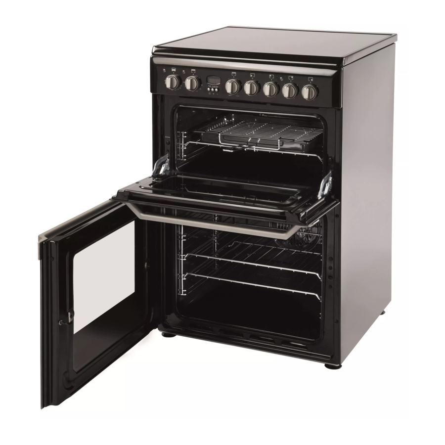
The model number and serial number are located on
the front of the cooker, as shown on the Feature's
page.
The cooker must be connected by a competent
person such as one who is a, NICEIC registered
contractor to a suitable double-pole control unit with
a minimum rating of 32A and a minimum contact
clearance of 3mm (applicable to newer properties,
older properties where a 30A double pole control unit
and a minimum contact clearance of 3mm is
acceptable).
The double pole control unit should be fitted
adjacent to the cooker, in accordance with IEE
regulations. The control unit must be within 2 metres
of but not directly above the appliance and should
be easily accessible in the event of an emergency.
The power supply cable should conform to B.S.6004
with a conductor size of 6mm2, minimum.
Access to the mains terminals is gained by
removing the rear access cover. The mains cable
must pass through the cable clamp adjacent to the
terminal block. Sufficient cable should be used to
allow the cooker to be pulled out for servicing.
Ensure that the mains cable is routed away
from any brackets affixed to the rear panel and
is not trapped to the rear wall when pushing the
cooker into position between cabinets.
Levelling
Four skid feet are fitted which can be adjusted up or
down to level the cooker.
For a correct installation of the cooker the following
precautions must be followed:
The height of the cooker can be adjusted by means
of adjustable feet in the plinth (900mm - 920mm).
Adjust the feet by tilting the cooker from the side.
Then install the product into position.
NOTE: This appliance must not be fitted on a
platform.
CAUTION:
CAUTION:
CAUTION: Some soft floor coverings may get
CAUTION:
CAUTION:
damaged if the cooker is not moved carefully.
Badly leveled device may increase condensation.
NOTE:
NOTE: Ensure oven shelves are level by using a
NOTE:
NOTE:
NOTE:
spirit level on the rod shelves.
6
This operation must be perfomed
by a qualified technician
Siting the Cooker
The cooker is designed to fit between kitchen
cabinets spaced 600mm apart. The space either
side need only be sufficient to allow withdrawal of
the cooker for servicing and cleaning.
It can be used with cabinets one side or both as well
as in an angled corner setting. It can also be used
freestanding.
Adjacent side walls which project above hob level,
must not be nearer to the cooker than 150mm and
should be protected by heat resistant material. Any
overhanging surface or cooker hood should not be
nearer than 650mm.
Note: This appliance must NOT be fitted on a
platform.
Moving the Cooker
Before moving your cooker, switch off at the cooker
control unit, ensure that it is cool.
Open the grill door sufficiently to allow a comfortable
grip on the underside front edge of the oven roof,
avoiding any grill elements.
Radio Interference
This appliance conforms to EN 55014 regarding
suppression of radio and television interference.
Note: Take care in moving the cooker as it is
heavy. Take care to ensure that any floor
covering is not damaged.
The appliance must not be installed behind
20
a decorative door in order to avoid overheating
Metal cover
After installing the power cable, screw the metal cover
150
650
with three screws.
600