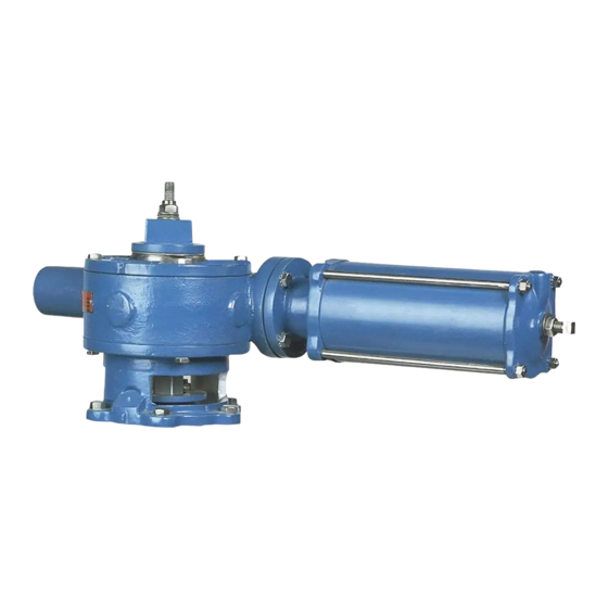
MANUAL G-SERIES ACTUATORS FOR USE WITH PTW & PFW TAPERED PLUG VALVES
Stop Adjustments
Note: If the operator does not turn easily when pushing on the stop, the cover has rusted to
the housing. Use a hammer and chisel to move the cover until the desired stop setting
is obtained.
3. Tighten the four screws loosened in Step 1.
4. Check the stop settings by turning the operator on the side of the actuator until the pointer
contacts each stop; ensure the valve plug position is correct at both stop settings.
Plug Clearance Adjustment
See the ADJUSTMENTS Section of the Valve Instruction for details on adjusting seat/plug clearance.
Actuator Removal
When a tapered plug valve is mounted in a vertical pipeline—or mounted in a horizontal
pipeline with the plug stem horizontal—gravity can cause the plug to swing to a lower
position in the valve body when the actuator is removed. Place the plug in the lowest
position before removing the actuator.
1. Discontinue system flow and relieve pipeline pressure.
2. Scribe a line on the valve bonnet and actuator adaptor to use for alignment during actuator
installation.
3. Unscrew the nut from the top of the wrenching square.
4. Take out the four socket head screws and remove the wrenching square.
5. Note the position of the pointer, then remove the two socket head screws and slide the pointer
off the actuator.
6. Unscrew the plug-adjusting nut from the stud and slide the bearing washer off the stud.
7. Note the stampings in the top of the valve plug stem. These stampings correspond with the plug
face as shown in Figure 1. It is important that the plug position be noted to ensure it is in the
correct position during ACTUATOR INSTALLATION.
8. Remove the screws fastening the adaptor to the adaptor plate (2" thru 4" valves) or to the valve
bonnet (5" thru 16" valves), then lift the actuator and adaptor off the valve.
August 2012
(continued)
Figure 1— Plug Stem Stampings
Page 5
DeZURIK
D10192

