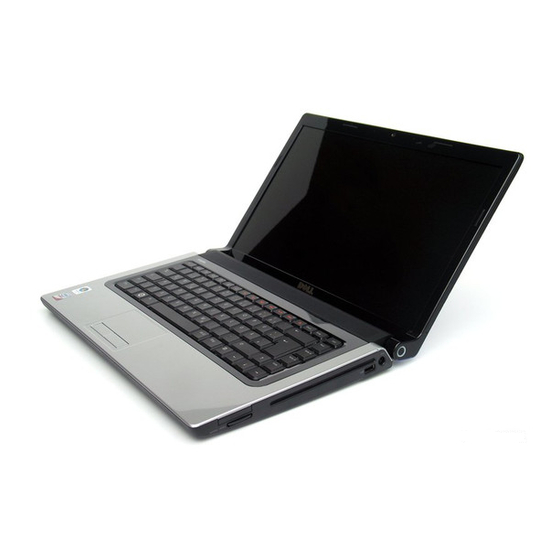
Dell 1555 - Studio - Chainlink Manuel d'entretien - Page 14
Parcourez en ligne ou téléchargez le pdf Manuel d'entretien pour {nom_de_la_catégorie} Dell 1555 - Studio - Chainlink. Dell 1555 - Studio - Chainlink 50 pages.
Également pour Dell 1555 - Studio - Chainlink : Manuel d'entretien (50 pages)

NOTE:
The original thermal pad can be reused if the original processor and heat sink are reinstalled together. If either the processor or heat sink is
replaced, use the thermal pad provided in the kit to ensure that thermal conductivity is achieved.
NOTE:
This procedure assumes that you have already removed the processor heat sink and are ready to replace it.
1. Align the four captive screws on the processor thermal-cooling assembly processor cover with the screw holes on the system board and tighten the
screws in sequential order.
2. Replace the system board to the computer base.
3. Replace the six screws that secure the system board to the computer base.
4. Connect the AC adapter connector cable, USB cable, fan cable, and the subwoofer cable to the system board (see
Assembly).
5. Connect the ExpressCard cables back to their respective connectors on the system board (see
6. Replace the optical drive (see
7. Slide the battery into the bay until it clicks into place.
Back to Contents Page
Replacing the Optical
Drive).
Replacing the System Board
Replacing the ExpressCard
Board).
