Allmatic BIOS1 BRT Manuel d'installation - Page 2
Parcourez en ligne ou téléchargez le pdf Manuel d'installation pour {nom_de_la_catégorie} Allmatic BIOS1 BRT. Allmatic BIOS1 BRT 12 pages. Programmable control board for barriers brt

1. Introduction
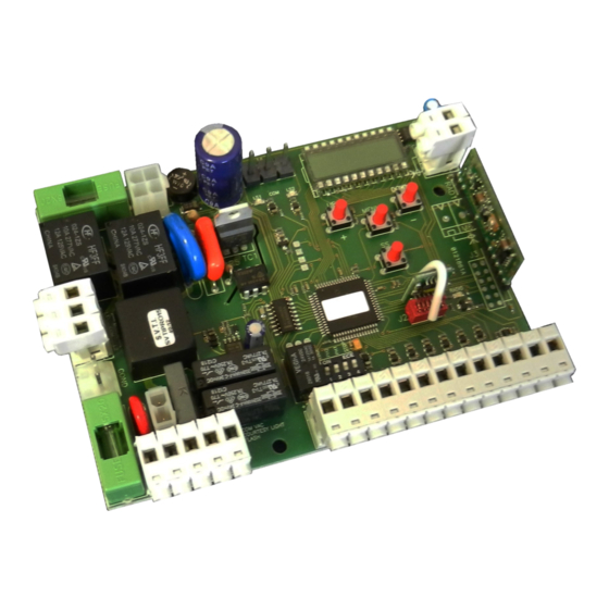
The control unit BIOS1 BRT is particularly indicated for barriers 230 Vac motor with maximum power absorbed of 700W. The control unit is equipped
with a display that allows a precise regulation of the thrust. The control unit can memorize up to 1000 transmitters (8000 as optional), with the step by
step, partial opening, open and close functions.
It is supplied with inputs for photocells, safety edge (mechanical or 8k2), magnetic loop, the buttons for step by step, partial opening, open, close and
stop. The outputs include a 230 Vac flashing light, courtesy light/zone light/open gate light, 24 Vdc accessories power supply.
ATTENTION: DO NOT INSTALL THE CONTROL UNIT WITHOUT READING THE INSTRUCTIONS FIRST !!!
THE INSTALLATION SHOULD BE PERFORMED ONLY BY QUALIFIED PERSONNEL.
Be sure that the limit switches are connected and correctly adjusted (see mechanical instruction)
2. Configuration
Accessories
FUSE
F 0.5 A
Line
FUSE
F 6.3 A
3. Connections
6-1622245
rev.3
23/12/2016
MOTOR OUTPUT
Connect the common of the motor to the clamp
motor COM of the control unit.
Connect the phase 1 of the motor to the clamp
motor L1 of the control unit.
Connect the phase 2 of the motor to the clamp
L2 of the control unit.
CAPACITOR
Connect the capacitor to the clamps COND of
the control unit.
LIMIT SWITCHES
Connect the NORMALLY CLOSED contact of
the limit switches to the control unit
ITA
ENG
FRA
SAFETY
DEVICES
DIP SWITCH
MEMORY
During the learning of the stroke phase the control
unit recognize itself the opening and closing limit
switch.
ESP
DEU
POR
Motor condensers 230 Vac
!Risk of electric shock!
2 / 12
