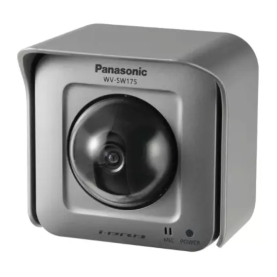
I Inside the dome cover
q LEDs (Indicators)
• Access indicator (green)
Blinks when the camera is accessed.
• Link indicator (orange)
Lights when the communication with a
network is established.
• SD memory card error indicator (red)
Lights when an error occurred in the SD
memory card.
w Indicators ON/OFF switch
Select "ON" or "OFF" to determine
whether or not to activate the link indica-
tor and the access indicator.
Important:
Select "ON" for normal use.
When "ON" is selected, it is possible to
turn on/off this switch using a PC via a
network. When the camera is used, set
the LED to OFF through your PC.
(Refer to the network operating instruc-
tions (PDF) for further information.)
e Monitor out connector (for adjustment)
(ø3.5mm mini jack)
This connector is provided only for
checking the adjustment the angular field
of view or the focus on the video monitor
when installing the camera or when serv-
icing. ( page 21)
r Image tilt adjustment ring
Use this ring to correct image tilt.
( page 26)
t SD memory card slot
Insert an SD memory card. ( page 28)
y Zoom ring
Use this ring to adjust the angular field of
view. ( page 27)
u Focus ring
Use this ring to adjust the focus.
( page 27)
14
i Tilting table
Rotate this table to adjust the tilting angle
of the camera. ( page 26)
o Panning table fixing screw [LOCK]
Fix the panning table with this screw after
adjusting the panning angle of the cam-
era. ( page 26)
!0 Panning table
Rotate this table to adjust the panning
angle of the camera. ( page 26)
I Dome cover
Protect the camera head with this dome
cover.
!1 Dome cover lock marker
( pages 18 - 20)
!2 Microphone hole
This hole is for microphone input (audio
capture).
Do
Otherwise, audio may become garbled.
!3 Inner dome
!4 Clear dome
Remove the cover film from the dome
cover after the installation is complete.
Do not touch the dome cover by hand
directly after removing the cover film.
I Mounting side
!7 External I/O terminals
Connect an external device to these ter-
minals. ( page 22)
!8 Power cord terminals
Connect the power cord from a DC12 V
or an AC 24 V power supply.
( page 21)
not
block
this
hole.

