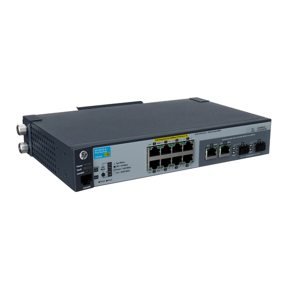
HP ProCurve 2615-8-PoE Manuel d'installation rapide
Parcourez en ligne ou téléchargez le pdf Manuel d'installation rapide pour {nom_de_la_catégorie} HP ProCurve 2615-8-PoE. HP ProCurve 2615-8-PoE 6 pages. 8-port switches
Également pour HP ProCurve 2615-8-PoE : Manuel de sélection (2 pages), Spécifications (24 pages), Notes de mise à jour (14 pages)

HP 2530 8-Port Switches Quick Setup Guide
The switch drawings in this document are for illustration only and may not match your particular switch model.
For more detailed instructions and information to set up your switch, view or download the Installation and Getting Started
Guide for your switch at www.hp.com/networking/support.
1.
Unpack and check included parts.
2.
Prepare for installation. To avoid personal injury or product damage, review the "Installation Precautions" on page 3.
3
. Power on and verify Self-Test completes normally. The switch does not contain a power switch. It is turned on by
connecting the AC/DC power adapter.
4.
Install the Switch Hardware. Power off the switch before installing the switch hardware.
(Optional) Attach accessories: The following accessories can be installed on your HP 2530 8-port switch:
A cable guard (HP P/N J9700A) to provide security for the attached network cables.
■
A power shelf (HP P/N J9820A) to hold the AC/DC power adapter.
■
For instructions to install these accessories, see the documentation that is included with them.
Table or Desktop: Attach the four self-adhesive pads
(included in the accessory kit) to the bottom corners of the
switch and place the switch on a secure horizontal surface.
Wall or Under-Table: For wall or under-table mounting, use
a #1 Phillips (cross-head) screwdriver and the 20-mm M4 tap
screws (included). The screws should be positioned 90 mm
apart, with the screw heads approximately 2 mm away from
the mounting surface to allow the switch to slide onto the
screws. (Under-Table: After installation, a third screw may be
installed to prevent switch movement.)
Caution: For wall-mounting, the network ports must face up.
Do not mount the switch with ventilation ducts facing up or
down. (See "Installation Precautions" on page 3.)
Switch
■
Console port serial cable (DB-9 to RJ-45)
■
Accessory kit (installation hardware)
■
AC/DC power adapter module and power cord
■
Documentation kit
■
After Self-Test:
Power LED = On
Fault LED = Off
Test LED = Off
M-4 tap
screws
1
Ventilation
