EPC EPC90147 Manuel de démarrage rapide - Page 7
Parcourez en ligne ou téléchargez le pdf Manuel de démarrage rapide pour {nom_de_la_catégorie} EPC EPC90147. EPC EPC90147 14 pages.
QUICK START GUIDE
THERMAL CONSIDERATIONS
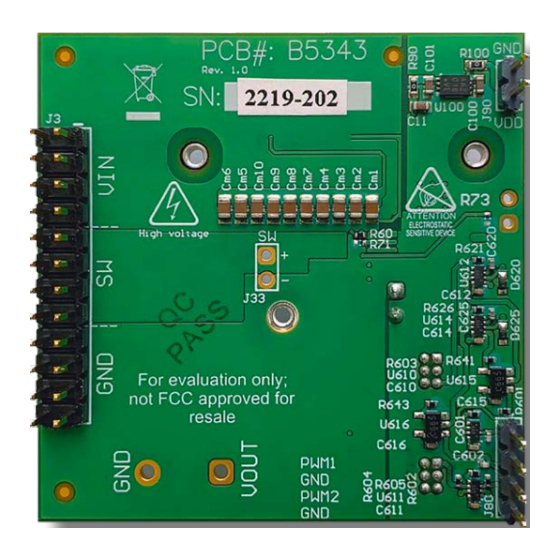
The EPC90147 board is equipped with three mechanical
spacers that can be used to easily attach a heat-spreader or
heatsink as shown in figure 9(a), and only requires a thermal
interface material (TIM), a custom shape heat-spreader/
heatsink, and screws. Prior to attaching a heat-spreader, any
component exceeding 1 mm in thickness under the heat-
spreader area will need to be removed from the board as
shown in figure 9 (b).
M2 screws (x3)
Insulator
Figure 9: Details for attaching a heatsink to the development board.
(a) 3D perspective, (b) top view details, (c) Assembled view with heat-
spreader attached.
EPC – POWER CONVERSION TECHNOLOGY LEADER |
Heat-spreader
SMD spacer (x3)
PCB
TIM
assembly
eGaN FETs (x2)
(a)
EPC-CO.COM
| ©2022 |
Components to remove prior
to Heat-spreader attach
Spacers for heat-spreader
20 mm
9.2 mm
attach
(b)
(c)
EPC90147
16.7 mm
| 7