EPC EPC90147 Skrócona instrukcja obsługi - Strona 7
Przeglądaj online lub pobierz pdf Skrócona instrukcja obsługi dla Płyta główna EPC EPC90147. EPC EPC90147 14 stron.
QUICK START GUIDE
THERMAL CONSIDERATIONS
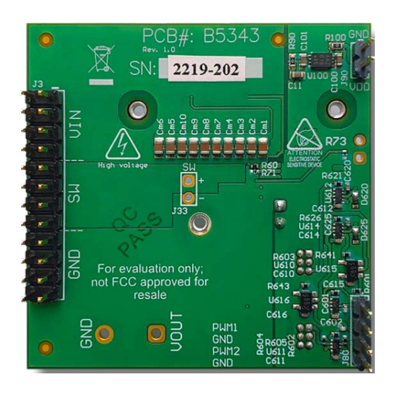
The EPC90147 board is equipped with three mechanical
spacers that can be used to easily attach a heat-spreader or
heatsink as shown in figure 9(a), and only requires a thermal
interface material (TIM), a custom shape heat-spreader/
heatsink, and screws. Prior to attaching a heat-spreader, any
component exceeding 1 mm in thickness under the heat-
spreader area will need to be removed from the board as
shown in figure 9 (b).
M2 screws (x3)
Insulator
Figure 9: Details for attaching a heatsink to the development board.
(a) 3D perspective, (b) top view details, (c) Assembled view with heat-
spreader attached.
EPC – POWER CONVERSION TECHNOLOGY LEADER |
Heat-spreader
SMD spacer (x3)
PCB
TIM
assembly
eGaN FETs (x2)
(a)
EPC-CO.COM
| ©2022 |
Components to remove prior
to Heat-spreader attach
Spacers for heat-spreader
20 mm
9.2 mm
attach
(b)
(c)
EPC90147
16.7 mm
| 7