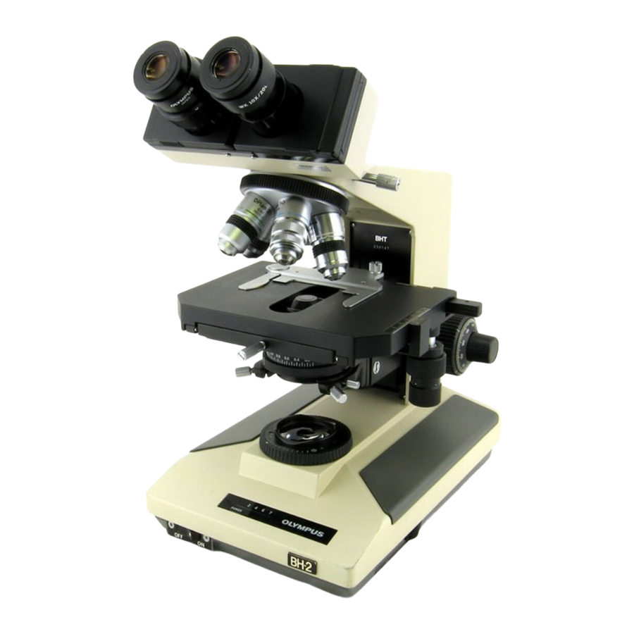
Olympus BH2 Series Démontage, nettoyage et remontage - Page 6
Parcourez en ligne ou téléchargez le pdf Démontage, nettoyage et remontage pour {nom_de_la_catégorie} Olympus BH2 Series. Olympus BH2 Series 45 pages. Phase contrast
Également pour Olympus BH2 Series : Manuel de dépannage et de réglage (46 pages), Démontage, nettoyage et remontage complets (23 pages), Démontage, nettoyage et remontage complets (40 pages), Manuel (6 pages), Manuel d'installation (9 pages)

Figure 137 - Carefully remove lower glass diffusion disk .............................................................................................. 33
Figure 138 - Place lower diffuser in the recess in barrel ............................................................................................... 33
Figure 139 - Place lower retaining ring into metal barrel ............................................................................................. 34
Figure 140 - Engage and snug the lower retaining ring ................................................................................................ 34
Figure 141 - Place collector lens into metal barrel ....................................................................................................... 34
Figure 142 - Install lower spacer tube into metal barrel ............................................................................................... 34
Figure 143 - Carefully place large diffuser disk into barrel ........................................................................................... 34
Figure 144 - Install the upper spacer tube into barrel .................................................................................................. 34
Figure 145 - Install adiabatic disk into the metal barrel ............................................................................................... 35
Figure 146 - Place upper retaining ring into position .................................................................................................... 35
Figure 147 - Snug upper retaining ring to the glass disk ............................................................................................... 35
Figure 148 - Ready to reinstall the Light Inlet Assembly ............................................................................................... 35
Figure 149 - Bite marks to act as alignment witness marks .......................................................................................... 35
Figure 150 - Insert Light Inlet Assembly into the bore .................................................................................................. 35
Figure 151 - Center the bite marks relative to the holes .............................................................................................. 36
Figure 152 - Reinstall setscrews to secure the barrel ................................................................................................... 36
Figure 153 - Top view of the Light Exit Assemblies ....................................................................................................... 36
Figure 154 - Bottom view of the Light Exit Assemblies ................................................................................................. 36
Figure 155 - Fully open the field diaphragm ................................................................................................................. 37
Figure 156 - Remove screws securing the filter holder................................................................................................. 37
Figure 157 - Lift and remove the filter holder ............................................................................................................... 37
Figure 158 - Lift and remove the field-adjustment ring ................................................................................................ 37
Figure 159 - Lens spanner tool with bent tips ............................................................................................................... 37
Figure 160 - Loosen the threaded retaining ring .......................................................................................................... 37
Figure 161 - Unscrew and remove threaded retaining ring .......................................................................................... 38
Figure 162 - Lift and remove the glass field-exit lens ................................................................................................... 38
Figure 163 - Blow loose dust from the glass lens .......................................................................................................... 38
Figure 164 - Clean both sides of the field-exit lens ....................................................................................................... 38
Figure 165 - Place field-exit lens back into the recess .................................................................................................. 38
Figure 166 - Engage the threaded retaining ring .......................................................................................................... 38
Figure 167 - Snug the threaded retaining ring .............................................................................................................. 39
Figure 168 - Remove screws securing frame to the base ............................................................................................. 39
Figure 169 - Carefully lift frame clear of the base casting ............................................................................................ 39
Figure 170 - Clean the area around the base cutout .................................................................................................... 39
Figure 171 - Thoroughly clean the light-exit frame ....................................................................................................... 39
Figure 172 - Blow all loose dust from the mirror surface ............................................................................................. 40
Figure 173 - Place the frame into a suitable catch pan ................................................................................................. 40
Figure 174 - Wet the reflective surface of the mirror ................................................................................................... 40
Figure 175 - Carefully clean the primary surface mirror ............................................................................................... 40
Figure 176 - Rinse the mirror with distilled/deionized water ....................................................................................... 40
Figure 177 - Blow away most of the rinse water .......................................................................................................... 40
Figure 178 - Thoroughly clean the field-adjustment ring ............................................................................................. 41
Figure 179 - Thoroughly clean the filter holder ............................................................................................................ 41
Figure 180 - Re-install Light Exit frame into base cutout .............................................................................................. 41
Figure 181 - Align holes in the frame with tapped holes .............................................................................................. 41
Figure 182 - Secure the Light Exit frame to the base .................................................................................................... 41
Figure 183 - Apply grease to brass surface in field ring ................................................................................................ 41
Figure 184 - Place the knurled field ring into position .................................................................................................. 42
Figure 185 - Apply oil to the plastic filter holder .......................................................................................................... 42
Figure 186 - Place the filter holder into recess of field ring .......................................................................................... 42
Figure 187 - Align holes in filter holder with tapped holes ........................................................................................... 42
Figure 188 - Field ring at maximum clockwise point ..................................................................................................... 42
Figure 189 - Field ring at maximum counterclockwise point ........................................................................................ 42
Teardown, Cleaning, and Reassembly of the Miscellaneous Parts of the Olympus BH-2 Microscope Frames
Revision 1
Page 6 of 45
