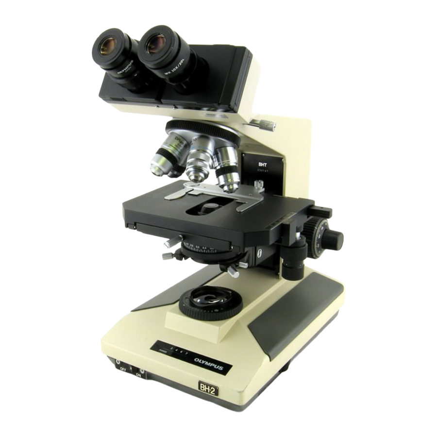
Olympus BH2 Series Демонтаж, очищення та повторний монтаж - Сторінка 6
Переглянути онлайн або завантажити pdf Демонтаж, очищення та повторний монтаж для Мікроскоп Olympus BH2 Series. Olympus BH2 Series 45 сторінок. Phase contrast
Також для Olympus BH2 Series: Посібник з усунення несправностей та налаштування (46 сторінок), Повний демонтаж, очищення та повторний монтаж (23 сторінок), Повний демонтаж, очищення та повторний монтаж (40 сторінок), Посібник (6 сторінок), Посібник з монтажу (9 сторінок)

Figure 137 - Carefully remove lower glass diffusion disk .............................................................................................. 33
Figure 138 - Place lower diffuser in the recess in barrel ............................................................................................... 33
Figure 139 - Place lower retaining ring into metal barrel ............................................................................................. 34
Figure 140 - Engage and snug the lower retaining ring ................................................................................................ 34
Figure 141 - Place collector lens into metal barrel ....................................................................................................... 34
Figure 142 - Install lower spacer tube into metal barrel ............................................................................................... 34
Figure 143 - Carefully place large diffuser disk into barrel ........................................................................................... 34
Figure 144 - Install the upper spacer tube into barrel .................................................................................................. 34
Figure 145 - Install adiabatic disk into the metal barrel ............................................................................................... 35
Figure 146 - Place upper retaining ring into position .................................................................................................... 35
Figure 147 - Snug upper retaining ring to the glass disk ............................................................................................... 35
Figure 148 - Ready to reinstall the Light Inlet Assembly ............................................................................................... 35
Figure 149 - Bite marks to act as alignment witness marks .......................................................................................... 35
Figure 150 - Insert Light Inlet Assembly into the bore .................................................................................................. 35
Figure 151 - Center the bite marks relative to the holes .............................................................................................. 36
Figure 152 - Reinstall setscrews to secure the barrel ................................................................................................... 36
Figure 153 - Top view of the Light Exit Assemblies ....................................................................................................... 36
Figure 154 - Bottom view of the Light Exit Assemblies ................................................................................................. 36
Figure 155 - Fully open the field diaphragm ................................................................................................................. 37
Figure 156 - Remove screws securing the filter holder................................................................................................. 37
Figure 157 - Lift and remove the filter holder ............................................................................................................... 37
Figure 158 - Lift and remove the field-adjustment ring ................................................................................................ 37
Figure 159 - Lens spanner tool with bent tips ............................................................................................................... 37
Figure 160 - Loosen the threaded retaining ring .......................................................................................................... 37
Figure 161 - Unscrew and remove threaded retaining ring .......................................................................................... 38
Figure 162 - Lift and remove the glass field-exit lens ................................................................................................... 38
Figure 163 - Blow loose dust from the glass lens .......................................................................................................... 38
Figure 164 - Clean both sides of the field-exit lens ....................................................................................................... 38
Figure 165 - Place field-exit lens back into the recess .................................................................................................. 38
Figure 166 - Engage the threaded retaining ring .......................................................................................................... 38
Figure 167 - Snug the threaded retaining ring .............................................................................................................. 39
Figure 168 - Remove screws securing frame to the base ............................................................................................. 39
Figure 169 - Carefully lift frame clear of the base casting ............................................................................................ 39
Figure 170 - Clean the area around the base cutout .................................................................................................... 39
Figure 171 - Thoroughly clean the light-exit frame ....................................................................................................... 39
Figure 172 - Blow all loose dust from the mirror surface ............................................................................................. 40
Figure 173 - Place the frame into a suitable catch pan ................................................................................................. 40
Figure 174 - Wet the reflective surface of the mirror ................................................................................................... 40
Figure 175 - Carefully clean the primary surface mirror ............................................................................................... 40
Figure 176 - Rinse the mirror with distilled/deionized water ....................................................................................... 40
Figure 177 - Blow away most of the rinse water .......................................................................................................... 40
Figure 178 - Thoroughly clean the field-adjustment ring ............................................................................................. 41
Figure 179 - Thoroughly clean the filter holder ............................................................................................................ 41
Figure 180 - Re-install Light Exit frame into base cutout .............................................................................................. 41
Figure 181 - Align holes in the frame with tapped holes .............................................................................................. 41
Figure 182 - Secure the Light Exit frame to the base .................................................................................................... 41
Figure 183 - Apply grease to brass surface in field ring ................................................................................................ 41
Figure 184 - Place the knurled field ring into position .................................................................................................. 42
Figure 185 - Apply oil to the plastic filter holder .......................................................................................................... 42
Figure 186 - Place the filter holder into recess of field ring .......................................................................................... 42
Figure 187 - Align holes in filter holder with tapped holes ........................................................................................... 42
Figure 188 - Field ring at maximum clockwise point ..................................................................................................... 42
Figure 189 - Field ring at maximum counterclockwise point ........................................................................................ 42
Teardown, Cleaning, and Reassembly of the Miscellaneous Parts of the Olympus BH-2 Microscope Frames
Revision 1
Page 6 of 45
