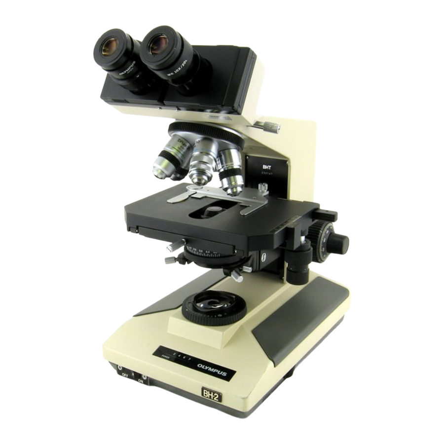
Olympus BH2 Series Демонтаж, очищення та повторний монтаж - Сторінка 4
Переглянути онлайн або завантажити pdf Демонтаж, очищення та повторний монтаж для Мікроскоп Olympus BH2 Series. Olympus BH2 Series 45 сторінок. Phase contrast
Також для Olympus BH2 Series: Посібник з усунення несправностей та налаштування (46 сторінок), Повний демонтаж, очищення та повторний монтаж (23 сторінок), Повний демонтаж, очищення та повторний монтаж (40 сторінок), Посібник (6 сторінок), Посібник з монтажу (9 сторінок)

Figure 31 - Carefully reinstall e-clip into plunger groove .............................................................................................. 14
Figure 32 - Remove mounting disk from dovetail recess .............................................................................................. 14
Figure 33 - Reinstall end-screw into knurled outer barrel ............................................................................................ 14
Figure 34 - Grip the knurling and tighten the end-screw .............................................................................................. 15
Figure 35 - Locking thumbscrew is ready for use .......................................................................................................... 15
Figure 36 - Protect the exposed optics with tissue ....................................................................................................... 15
Figure 37 - Protect the exposed optics with cardboard ................................................................................................ 15
Figure 38 - Remove e-clip from the end of thumbscrew .............................................................................................. 15
Figure 39 - Unscrew and remove the locking thumbscrew .......................................................................................... 16
Figure 40 - Clean the threads of the locking thumbscrew ............................................................................................ 16
Figure 41 - Clean the threads of the tapped hole ......................................................................................................... 16
Figure 42 - Apply grease to threads of the thumbscrew............................................................................................... 16
Figure 43 - Screw the thumbscrew into the tapped hole ............................................................................................. 16
Figure 44 - The ring groove for the retaining e-clip ...................................................................................................... 16
Figure 45 - Carefully reinstall the e-clip into ring groove .............................................................................................. 17
Figure 46 - Remove protection for the exposed optics ................................................................................................. 17
Figure 47 - Refurbished thumbscrew is ready for use .................................................................................................. 17
Figure 48 - Nosepiece slide mount (old style) ............................................................................................................... 17
Figure 49 - Nosepiece slide mount (new style) ............................................................................................................. 17
Figure 50 - Remove the nosepiece locking thumbscrew .............................................................................................. 17
Figure 51 - Nosepiece locking thumbscrews ................................................................................................................. 18
Figure 52 - Remove screws securing the slide mount ................................................................................................... 18
Figure 53 - Remove the slide mount from the pillar arm.............................................................................................. 18
Figure 54 - Clean tapped hole for the locking thumbscrew .......................................................................................... 18
Figure 55 - Clean threads of locking thumbscrew (old style) ........................................................................................ 18
Figure 56 - Thoroughly clean slide-mount base (old style) ........................................................................................... 19
Figure 57 - Slide-mount parts ready for use (old style) ................................................................................................. 19
Figure 58 - Remove the locking-block stop screw ......................................................................................................... 19
Figure 59 - Remove the locking-block pivot screw ....................................................................................................... 19
Figure 60 - Separate locking block from slide-mount base ........................................................................................... 19
Figure 61 - Thoroughly clean slide-mount base (new style) ......................................................................................... 19
Figure 62 - Clean the nosepiece locking block .............................................................................................................. 20
Figure 63 - Clean threads of the locking thumbscrew .................................................................................................. 20
Figure 64 - Position locking block under slide-mount base .......................................................................................... 20
Figure 65 - Reinstall the locking-block pivot screw ....................................................................................................... 20
Figure 66 - Reinstall the locking-block stop screw ........................................................................................................ 20
Figure 67 - Slide-mount parts ready for use (new style) ............................................................................................... 20
Figure 68 - Place the nosepiece slide mount into position ........................................................................................... 21
Figure 69 - Align drilled holes with tapped holes .......................................................................................................... 21
Figure 70 - Secure nosepiece slide mount with screws ................................................................................................ 21
Figure 71 - Lightly grease the thumbscrew threads ...................................................................................................... 21
Figure 72 - Reinstall the nosepiece locking thumbscrew .............................................................................................. 21
Figure 73 - Newly serviced slide mount ready for use .................................................................................................. 21
Figure 74 - Field-diaphragm assembly (old style) ......................................................................................................... 22
Figure 75 - Field-diaphragm assembly (new style) ........................................................................................................ 22
Figure 76 - Remove screws securing the field diaphragm ............................................................................................ 22
Figure 77 - Remove the field diaphragm assembly ....................................................................................................... 22
Figure 78 - Components of field diaphragm (old style) ................................................................................................ 22
Figure 79 - Remove the slotted diaphragm stop pin..................................................................................................... 23
Figure 80 - Remove two screws securing the gear collar .............................................................................................. 23
Figure 81 - Lift and remove the plastic gear collar ........................................................................................................ 23
Figure 82 - Remove screws securing brass plate to stator ............................................................................................ 23
Figure 83 - Lift and remove the brass retaining plate ................................................................................................... 23
Teardown, Cleaning, and Reassembly of the Miscellaneous Parts of the Olympus BH-2 Microscope Frames
Revision 1
Page 4 of 45
