Olympus BH2 Series Zerlegung, Reinigung und Wiederzusammenbau - Seite 4

Blättern Sie online oder laden Sie pdf Zerlegung, Reinigung und Wiederzusammenbau für Mikroskop Olympus BH2 Series herunter. Olympus BH2 Series 45 Seiten. Phase contrast
Auch für Olympus BH2 Series: Handbuch zur Fehlersuche und -anpassung (46 seiten), Vollständige Demontage, Reinigung und Wiedermontage (23 seiten), Vollständige Demontage, Reinigung und Wiedermontage (40 seiten), Handbuch (6 seiten), Installationshandbuch (9 seiten)
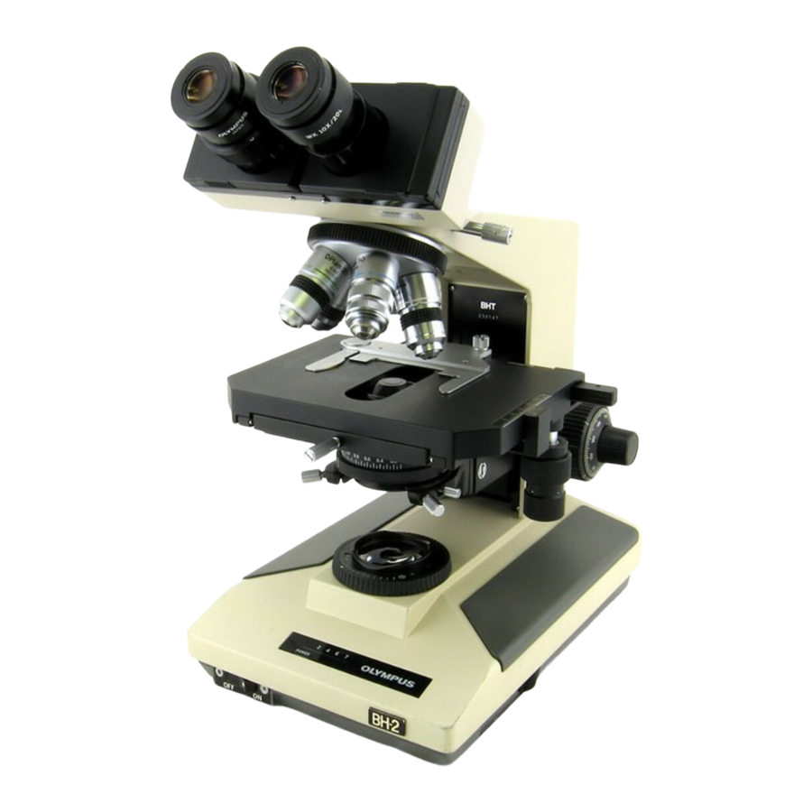
Olympus BH2 Series Zerlegung, Reinigung und Wiederzusammenbau
Figure 31 - Carefully reinstall e-clip into plunger groove .............................................................................................. 14
Figure 32 - Remove mounting disk from dovetail recess .............................................................................................. 14
Figure 33 - Reinstall end-screw into knurled outer barrel ............................................................................................ 14
Figure 34 - Grip the knurling and tighten the end-screw .............................................................................................. 15
Figure 35 - Locking thumbscrew is ready for use .......................................................................................................... 15
Figure 36 - Protect the exposed optics with tissue ....................................................................................................... 15
Figure 37 - Protect the exposed optics with cardboard ................................................................................................ 15
Figure 38 - Remove e-clip from the end of thumbscrew .............................................................................................. 15
Figure 39 - Unscrew and remove the locking thumbscrew .......................................................................................... 16
Figure 40 - Clean the threads of the locking thumbscrew ............................................................................................ 16
Figure 41 - Clean the threads of the tapped hole ......................................................................................................... 16
Figure 42 - Apply grease to threads of the thumbscrew............................................................................................... 16
Figure 43 - Screw the thumbscrew into the tapped hole ............................................................................................. 16
Figure 44 - The ring groove for the retaining e-clip ...................................................................................................... 16
Figure 45 - Carefully reinstall the e-clip into ring groove .............................................................................................. 17
Figure 46 - Remove protection for the exposed optics ................................................................................................. 17
Figure 47 - Refurbished thumbscrew is ready for use .................................................................................................. 17
Figure 48 - Nosepiece slide mount (old style) ............................................................................................................... 17
Figure 49 - Nosepiece slide mount (new style) ............................................................................................................. 17
Figure 50 - Remove the nosepiece locking thumbscrew .............................................................................................. 17
Figure 51 - Nosepiece locking thumbscrews ................................................................................................................. 18
Figure 52 - Remove screws securing the slide mount ................................................................................................... 18
Figure 53 - Remove the slide mount from the pillar arm.............................................................................................. 18
Figure 54 - Clean tapped hole for the locking thumbscrew .......................................................................................... 18
Figure 55 - Clean threads of locking thumbscrew (old style) ........................................................................................ 18
Figure 56 - Thoroughly clean slide-mount base (old style) ........................................................................................... 19
Figure 57 - Slide-mount parts ready for use (old style) ................................................................................................. 19
Figure 58 - Remove the locking-block stop screw ......................................................................................................... 19
Figure 59 - Remove the locking-block pivot screw ....................................................................................................... 19
Figure 60 - Separate locking block from slide-mount base ........................................................................................... 19
Figure 61 - Thoroughly clean slide-mount base (new style) ......................................................................................... 19
Figure 62 - Clean the nosepiece locking block .............................................................................................................. 20
Figure 63 - Clean threads of the locking thumbscrew .................................................................................................. 20
Figure 64 - Position locking block under slide-mount base .......................................................................................... 20
Figure 65 - Reinstall the locking-block pivot screw ....................................................................................................... 20
Figure 66 - Reinstall the locking-block stop screw ........................................................................................................ 20
Figure 67 - Slide-mount parts ready for use (new style) ............................................................................................... 20
Figure 68 - Place the nosepiece slide mount into position ........................................................................................... 21
Figure 69 - Align drilled holes with tapped holes .......................................................................................................... 21
Figure 70 - Secure nosepiece slide mount with screws ................................................................................................ 21
Figure 71 - Lightly grease the thumbscrew threads ...................................................................................................... 21
Figure 72 - Reinstall the nosepiece locking thumbscrew .............................................................................................. 21
Figure 73 - Newly serviced slide mount ready for use .................................................................................................. 21
Figure 74 - Field-diaphragm assembly (old style) ......................................................................................................... 22
Figure 75 - Field-diaphragm assembly (new style) ........................................................................................................ 22
Figure 76 - Remove screws securing the field diaphragm ............................................................................................ 22
Figure 77 - Remove the field diaphragm assembly ....................................................................................................... 22
Figure 78 - Components of field diaphragm (old style) ................................................................................................ 22
Figure 79 - Remove the slotted diaphragm stop pin..................................................................................................... 23
Figure 80 - Remove two screws securing the gear collar .............................................................................................. 23
Figure 81 - Lift and remove the plastic gear collar ........................................................................................................ 23
Figure 82 - Remove screws securing brass plate to stator ............................................................................................ 23
Figure 83 - Lift and remove the brass retaining plate ................................................................................................... 23
Teardown, Cleaning, and Reassembly of the Miscellaneous Parts of the Olympus BH-2 Microscope Frames
Revision 1
Page 4 of 45