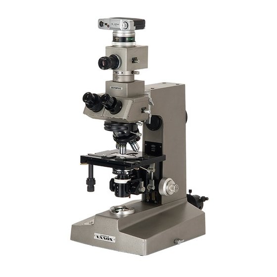
Olympus VANOX Manuel d'instruction - Page 19
Parcourez en ligne ou téléchargez le pdf Manuel d'instruction pour {nom_de_la_catégorie} Olympus VANOX. Olympus VANOX 28 pages. Universal research microscope

€3.
Center the Light Bulb
1)
First, make sure that the swing-out frosted
glass
at
the Fight exit on the microscope base
i s
disengaged, and that
the
swing-out auxiliary
lens inside the base
IS
in the light path (lever
in vertical position).
2)
Insert thecenteringfrosted glassinto thefilter
mount
at
the
light exit.
3)
Loosen the clamping
screw
of the lamp
socket
m
F
IS.
12
and move the socket back and forth t o focus
the bulb filament on the frosted glass. Adjust the light intensity, so
that the
filament can
be
easily recognized. Clamp the lamp socket.
4)
Center the filament image with the two
coaxial centering knobs on the lamp
socket. (Fig. 12)
5)
Removecenteringfrostedglass.
Repeat
the above procedure
after
instal lat~on of
a
replacement
bu
Ib.
Rulb Replacement Procedure
1)
Loosen the sockct clamplng screw and s f ~ d e out
the socket.
21
Remove
the bulb by slightly depress~ng
~t
agalnst
the wat and then rotating ~t In a counterclockw~se direct~on
3 1
Insert replacement
bulb
In
rcvprsed order,
Before
use,
wipe
off
thororlghly any f~ngerprrnrs or stains on
tne
bulb
Fuse Replacement
At the
back of
the SOOVAC ourput s o c k ~ t ,
a
fuse
holder 1 s posit~oned. When the fuse
rs
burned, slide the mlcroscope
to the desk edge
on
whlch the
rnlcrwcope
IS
placed,
u n t ~ l there
IF
an openrng
at the bottom
of the microxope base
enouqh
to
realace rhe burned f u ~ e with
a new one
from 'beneath
the b m Or lay
Onwn
the
mlcroscope
*
Remove the observat~on tube, stage, etc, prlor t o replacement of the
fuse
C.
Center the Condenser
1 )
The frosted glass at the light exit
should be swung out of the light path
and
the swing-out auxiliary lens should be engaged {lever
in
vertical
position}.
2)
Push in the light path selector knob on the binocular tube all the way
(white band).
3)
Place a specimen on the mechanical stage and use
the
objective
1bX
t o
bring
the
specimen in focus.
4)
Raise
the
condenser all
the
way with the condenser height adjustment knob.
5)
Swing the auxiliary lens system t o position L and stop down the field
iris diaphragm with the knurled ring.
A slightly blurred image of the
field diaphragm can now be seen
in
the eyepiece.
6)
Move t h e condenser
up
and down
t o
focus on t h e image of the field iris
diaphragm.
7) While widening the diameter of the field progressively, use the condenser
centering knobs to bring the diaphragm image into the center of the field
of v i m .
If the polygonal image o f the iris diaphragm becomes inscribed
in the
field it means
that the field diaphragm i s centered. Slightly increase
diameter of field iris diaphragm until i t is just outside the field of view.
