Axminster RTC7030 Manuel de l'utilisateur - Page 8
Parcourez en ligne ou téléchargez le pdf Manuel de l'utilisateur pour {nom_de_la_catégorie} Axminster RTC7030. Axminster RTC7030 16 pages. 305mm & 750mm sheet metal workers

Operating Instructions...
W
A X M I N S T E R
W H I T E
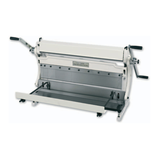
The basic operation of the machine is as follows. The operating handle is attached to a
shaft which serves two functions; firstly it drives the three rollers which carry out the rolling
operation and secondly, with the aid of eccentrics, mounted at the two ends, it raises and
lowers the lower cross bar of the machine. Mounted on the top of this cross bar are the
female bending dies whilst the lower edge carries the upper shear blade. The male bending
dies are fixed to the static cross beam and the lower shear blade is fixed to the table on
which the work is supported. Thus, as the handle is operated, the rolls rotate to form
cylindrical items whilst the main beam goes up and down to either form bends between the
two dies or to shear material between the moving and fixed blades.
Shearing
Shearing can be carried out either by positioning the material between the blades by eye
using a line marked on the sheet or by using the adjustable backstop for more precise
results.
To fit the backstop assembly, screw the two rods into the rear of the static cross beam
(see fig 5), fit the two blocks to the backstop bar with two hex screws (see fig 6) and slide
the bar onto the two rods (see fig 7). The two clamping screws are used to secure the
backstop in the required position on the two rods. Please note that the flange of the
backstop bar should be positioned downwards.
If a precise 90 deg angle is required, the guide block can be fitted to the right hand side of
the table using hex screws. (see fig 8). The guide block should be set square to the lower
blade using an engineer's square.
To carry out the shearing operation, raise the cross beam to its highest position, slide the
material in between the blades, position it correctly either with the marked line or up against
the back stop and rotate the operating handle to make the cut.
NOTE: If you find that the rollers are not rotating all the way round while sheet
bending, it's because the pressure plate that clamps the material during
!
shearing, binds up on it's springs & the handle can not be turned completely
over. If this accrues, remove the pressure plate.
Bending
As with the shearing operation, bending can either be carried out by lining up the work by
eye or by positioning it with the help of the backstop. If the backstop is to be used it should
be positioned in the upper holes (see fig 7) and the backstop bar reversed so that the
flange is upwards.
Having positioned the workpiece correctly between the bending dies, rotate the handle to
bring the dies together to form the bend. The angle of the bend, up to a maximum of 90
deg., is controlled by limiting the travel of the upper die. If repetition work is to be carried
out then the bend angle can be set by adjusting the height of the cross beam using
adjusting screws shown (see fig 9b).
If it is required to bend only part of the workpiece, as shown in fig. 9, then the appropriate
sections of the upper die can be removed by undoing the hex bolts (see Fig. 9a). When
forming this type of bend it will be necessary to notch the corner as shown in figs 10 & 10a
07
to achieve the required result.
