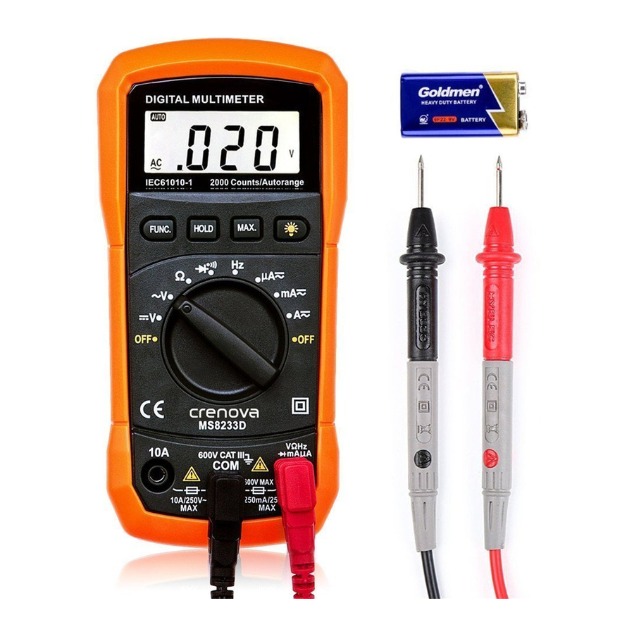
Crenova MS8233D Instructions d'utilisation - Page 10
Parcourez en ligne ou téléchargez le pdf Instructions d'utilisation pour {nom_de_la_catégorie} Crenova MS8233D. Crenova MS8233D 12 pages.

contact resistance value from the measured value.
● For high-resistance measurement (>10MΩ), it is normal taking several
second to obtain stable reading.
● The LCD display "OL" indicating open-circuit for the tested resistor or
the resistor value is higher than the maximum range of the meter.
5-3. Diode/Continuity check
5.3.1. Diode
① Set the rotary switch to "
diode check mode. You can enter the continuity check mode by the
" FUNC" Key.
② insert the red test lead into the "VΩ" terminal and the black test lead into
the "COM" terminal.
③ Use the diode test mode to check diodes, transistors and other
semiconductor device. In the diode test mode sends a current through the
semiconductor junction, and the measure the voltage drop across the
junction. A good silicon junction drop between 0.5V and 0.8V.
④ For forward voltage drop reading on any semiconductor component, place
the red test lead on the component anode and place the black test lead on
the component cathode. The measured value show on the display.
⑤ Reverse the test lead and measure the voltage across the diode again.
● If diode is good, the display shows "OL".
● If diode is shorted, the display shows 0 (zero) in both direction.
● If display shows "OL" in both direction, the diode is open.
5.3.2. Continuity Check:
① Press the "FUNC" key to enter to the continuity mode.
② The buzzer sound if the resistance of a circuit under test is less than 100Ω.
5-4. Frequency measurement
① Set the rotary switch to "Hz" position.
② Insert the red test lead into the " VΩHz" input terminal and the black test
lead into the "COM" terminal.
③ Connect the test leads across with the circuit under testing. The measured
value shown on the LCD display.
" position. First time, default mode is
9
