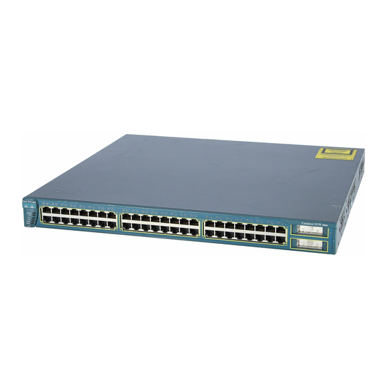
Cisco Catalyst 3550 Manuel de démarrage - Page 18
Parcourez en ligne ou téléchargez le pdf Manuel de démarrage pour {nom_de_la_catégorie} Cisco Catalyst 3550. Cisco Catalyst 3550 33 pages. Cisco catalyst 3550: supplementary guide
Également pour Cisco Catalyst 3550 : Bulletin d'information sur les produits (3 pages), Bulletin d'information sur les produits (5 pages), Fiche technique (21 pages)

Slide the exposed area of the 6-gauge wire
Step 3
into the ground lug, and use the crimping
tool to crimp the lug to the wire.
Using the ratcheting screwdriver, torque the ground lug screws to 15 lbf-in. (240
Step 4
ounce-force inches [ozf-in.]) to attach the ground lug to the switch.
Wiring the DC Input Power Source
Follow these steps:
On the terminal block connector, identify the positive and negative feed positions.
Step 1
Step 2
Strip each of the four wires coming from the
DC power source to 0.27 inch (6.6 mm)
± 0.02 inch (0.5 mm). Do not strip more
than the recommended amount of wire.
Insert the four exposed wires from the DC-input power source into the terminal block plug,
Step 3
matching positive to positive and negative to negative for both the A and the B feed wires.
18
0.27 inch (6.6 mm)
