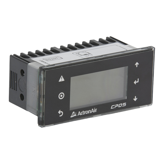
ActronAir CP05 Manuel d'installation - Page 8
Parcourez en ligne ou téléchargez le pdf Manuel d'installation pour {nom_de_la_catégorie} ActronAir CP05. ActronAir CP05 16 pages. Control interface

CP05 & CP10 CONTROL INTERFACE INSTALLATION GUIDE
DATA CABLE AND RJ12 PLUG PREPARATION:
Option 1 - Data Cable with RJ12 plug at both end:
VIEW
FROM CABLE END
6
5
4
3
2
1
RJ12 Plug
(Installer to Provide)
VIEW
FROM CABLE END
6
5
4
3
2
1
RJ12 Plug
(Installer to Provide)
Option 2 - Data Cable with RJ12 plug at one end (For Secondary Control Interface):
VIEW
FROM CABLE END
6
5
4
3
2
1
RJ12 Plug
(Installer to Provide)
VIEW
FROM CABLE END
6
5
4
3
2
1
RJ12 Plug
(Installer to Provide)
RJ12 Terminal Connections A:
• Terminal 1:- Connect to +Vdc on the connector block.
• Terminal 2:- Connect to GND on the connector block.
• Terminal 3:- Connect to RX-/TX- on the connector block.
• Terminal 4:- Connect to RX+/TX+ on the connector block.
• Terminal 5:- Connect to GND on the connector block.
• Terminal 6:- Connect to +Vdc on the connector block.
8
6 Core Flat 7/0.12 (AWG28) Telephone Cable
50m Max. Length - Field Scope
(Installer to Provide)
See RJ12 Terminal Connections A below.
6 Core (3 Pair) Twisted Pair 7/0.20 (AWG24) Shielded Data Cable
200 Max. Length - Field Scope
(Installer to Provide)
See RJ12 Terminal Connections B below.
6 Core Flat 7/0.12 (AWG28) Telephone Cable
50m Max. Length - Field Scope
(Installer to Provide)
See RJ12 Terminal Connections A below.
6 Core (3 Pair) Twisted Pair 7/0.20 (AWG24) Shielded Data Cable
200 Max. Length - Field Scope
(Installer to Provide)
See RJ12 Terminal Connections B below.
FROM CABLE END
6
5
4
3
2
1
(Installer to Provide)
FROM CABLE END
6
5
4
3
2
1
(Installer to Provide)
TERMINAL 11
6
5
4
3
2
1
TERMINAL 14
GND
6
5
4
3
2
1
TERMINAL 14
GND
RJ12 Terminal Connections B:
• Terminal 1:- Connect to +Vdc on the connector block.
• Terminal 2:- Connect to GND on the connector block.
• Terminal 3:- Connect to RX-/TX- on the connector block.
• Terminal 4:- Connect to RX+/TX+ on the connector block.
• Terminal 5:- Connect to GND on the connector block.
• Terminal 6:- Connect to +Vdc on the connector block.
VIEW
RJ12 Plug
VIEW
RJ12 Plug
NOTE:
19 20 21 22
Use these terminals for
Tri-Capacity models.
RX+ / TX+
TERMINAL 12
RX- / TX-
ELECTICAL
PANEL
11
12
13
14
TERMINAL 13
+Vdc
TERMINAL 11
RX+ / TX+
TERMINAL 12
RX- / TX-
ELECTICAL
PANEL
11
12
13
14
TERMINAL 13
+Vdc
Twisted Pair
Twisted Pair
Twisted Pair
CP05 - CP10 Control Interface Insert
Doc. No.0525-035 Ver. 6 220307
To
CM100
or uPC
To
CM100
or uPC
