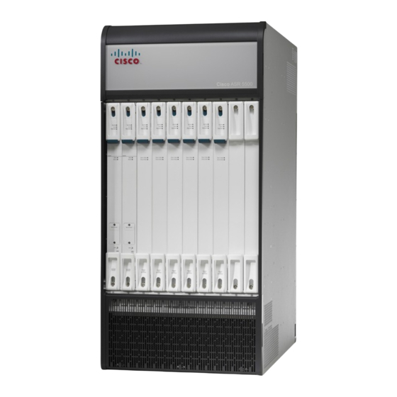
Cisco ASR 5500 Aperçu de la procédure d'installation
Parcourez en ligne ou téléchargez le pdf Aperçu de la procédure d'installation pour {nom_de_la_catégorie} Cisco ASR 5500. Cisco ASR 5500 6 pages.
Également pour Cisco ASR 5500 : Manuel d'installation (31 pages)

Installation Procedure Overview
This chapter briefly describes the steps and tools that are required to install the ASR 5500 chassis.
Caution
The copper serial Console port, 1000Base-T management ports, and CO alarm interface of the ASR 5500
are suitable for connection to intra-building or unexposed wiring or cabling only. These ports MUST NOT
be metallically connected to interfaces that connect to the outside plant (OSP) or its wiring. These interfaces
are designed for use as intra-building interfaces only (Type 2 or Type 4 ports as described in
GR-1089-CORE, Issue 5) and require isolation from the exposed OSP cabling. The addition of Primary
Protectors is not sufficient protection in order to connect these interfaces metallically to OSP wiring.
It includes the following sections:
•
•
•
•
•
Installation Sequence
Installation of the ASR 5500 requires the completion of the following procedures:
1 Unpack the chassis and cards.
2 Determine which chassis mounting option to use: flush or mid-mount. Reposition the mounting brackets
if necessary.
3 Install the chassis into a standard 19-inch equipment rack or telecommunications cabinet.
4 Connect the chassis ground point to site ground.
5 Optional: Install the Cable Management System.
6 Install SSC and FSC cards into the front of the chassis.
7 Install MIO/UMIO cards and DPC/UDPCs or DPC2/UDPC2s into the rear of the chassis.
Installation Sequence, page 1
Required Tools and Equipment, page 2
Site Prerequisites, page 3
ESD Precautions, page 4
Standards Compliance, page 5
ASR 5500 Installation Guide
1
