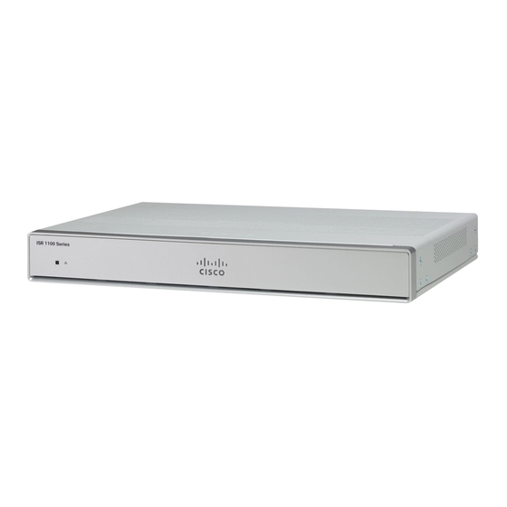
Cisco C1101-4P Installation et raccordement - Page 25
Parcourez en ligne ou téléchargez le pdf Installation et raccordement pour {nom_de_la_catégorie} Cisco C1101-4P. Cisco C1101-4P 27 pages. Install and upgrade internal modules and field replaceable units
Également pour Cisco C1101-4P : Manuel (12 pages)

Install and Connect the Router
Enter Ctrl-a followed by : then quit
Connect WAN and LAN Interfaces
This section describes how to connect WAN and LAN interface cables. Before you connect the interface
cables, refer to the following warning statements:
Warning
Never install telephone jacks in wet locations unless the jack is specifically designed for wet locations.
Statement 1036.
Warning
Never touch uninsulated telephone wires or terminals unless the telephone line has been disconnected at the
network interface. Statement 1037.
Warning
For connections outside the building where the equipment is installed, the following ports must be connected
through an approved network termination unit with integral circuit protection, LAN, PoE. Statement 1044.
Warning
Avoid using or servicing any equipment that has outdoor connections during an electrical storm. There may
be a risk of electric shock from lightning. Statement 1088.
Ports and Cabling
This section summarizes typical WAN and LAN connections for Cisco 1100 Series ISRs. The connections
summarized here are described in detail in the Cisco Modular Access Router Cable Specifications document
on cisco.com.
Table 3: WAN and LAN Connections
Port or Connection
Ethernet
Gigabit Ethernet SFP,
optical
Gigabit Ethernet SFP,
copper
xDSL
(VDSL2 / ADSL2/2+)
1
Port Type, Color
Connection
RJ-45, yellow
Ethernet hub or Ethernet
switch
LC, color according to
1000BASE-SX, -LX, -LH,
optical wavelength
-ZX, -CWDM
RJ-45
1000BASE-T
RJ-11
POTS or ISDN line
Connect WAN and LAN Interfaces
Cable
Category 5 or higher
Ethernet
Optical fiber as specified on
applicable data sheet
Category 5, 5e, 6 UTP
RJ-11 telephone cable
Install and Connect the Router
25
