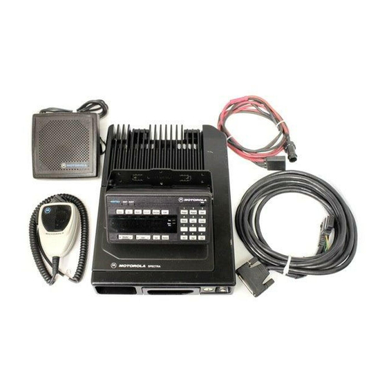
Motorola ASTRO Digital Spectra Manuel d'installation - Page 10
Parcourez en ligne ou téléchargez le pdf Manuel d'installation pour {nom_de_la_catégorie} Motorola ASTRO Digital Spectra. Motorola ASTRO Digital Spectra 32 pages. Fm two-way mobile radios
Également pour Motorola ASTRO Digital Spectra : Liste des pièces (13 pages)

Installation
Planning the
Installation
Speaker Installation
NOTE:
In this manual, all information relating to a specific
control-head model (A3, A4, A5, A7, or A9) will be
applicable to a similar control head in the ASTRO Digital
Spectra and Spectra radio families. Examples, A4
control head installation is also applicable to control
heads B4, E4, and W4 control heads; A7 control head
installation is also applicable to control heads B7, E7,
and W7.
Figures 2 through 7 show all the possible configurations. The title under
each figure identifies which power radio and which model control head is
being shown and whether the radio can be remote or dash mounted
(only low-/mid-power radios can be dash mounted). Identify which of the
first six figures shows the configuration being installed and use the
diagram when planning the installation.
The Spectra radio should operate only in negative ground electrical
systems. Check the ground polarity of the vehicle before starting the radio
installation making sure the polarity is correct. Accidentally reversing the
polarity will not damage the radio, but will cause the cable fuses to blow.
DO NOT ground the radio's speaker leads. This system
has a floating speaker output (dc voltage on both leads);
!
damage to the audio circuit will result if either lead is
grounded or if they are shorted together.
C a u t i o n
The speaker kit includes a trunnion bracket that allows the speaker to be
mounted in a variety of ways. With the trunnion bracket, the speaker can
mount permanently on the dashboard or in accessible firewall areas. The
trunnion allows the speaker to tilt for best operation. Mount the speaker out
of the way so that it will not be kicked or knocked around by the vehicle
occupants. Mount the speaker as follows:
1. Use the speaker mounting bracket as a template to mark the mounting
hole locations.
2. Use the self-drilling screws provided to fasten the trunnion.
3. Attach the speaker and fasten to the trunnion with two wing screws.
4. Route the speaker wires under the carpet or floor covering, or behind
the kick panels. Be sure the wires are out of the way and will not be
snagged and broken by the occupants of the vehicle.
2
4
