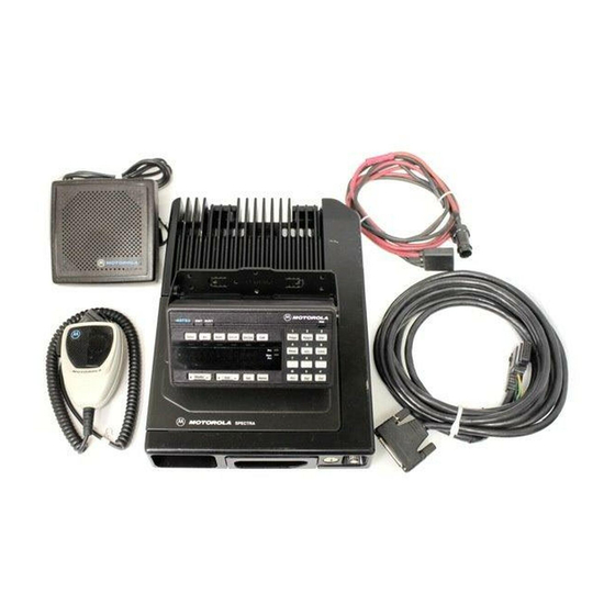
Motorola ASTRO Digital Spectra Manuel d'installation - Page 8
Parcourez en ligne ou téléchargez le pdf Manuel d'installation pour {nom_de_la_catégorie} Motorola ASTRO Digital Spectra. Motorola ASTRO Digital Spectra 32 pages. Fm two-way mobile radios
Également pour Motorola ASTRO Digital Spectra : Liste des pièces (13 pages)

Radio Dimensions
Base/Control
Stations
2
The Spectra and ASTRO Spectra Radios have the following dimensions
(H x W x D):
15-watt – 2.0" x 7.1" x 7.5"
20- to 35-watt and 40-watt – 2.0" x 7.1" x 8.6"
Model charts for the different versions are found in the basic service
manual. "Versions" are identified by the model number "suffix." Although
the charts are very similar, there are subtle but very important differences.
Determine from the radio's identification label, which model control head
and version is yours. Keep this information handy for future references.
Determine the model and version of the radio as follows:
For outdoor antenna installations, proper site grounding and
lightning protection are vitally important. Failure to provide
!
proper lightning protection may result in permanent damage
to the radio equipment. Refer to Motorola Quality Standards
C a u t i o n
Fixed Network Equipment Installation Manual R56
(6881089E50), for complete information regarding lightning
protection.
•
The antenna should be mounted outside the building on the roof or a
tower if at all possible and the antenna cable should be earth
grounded.
•
The radio chassis must be earth grounded and a lightning surge
protector should be used in line with the radio connector and the
outdoor antenna. The lightning surge protector should be earth
grounded and located at the point where the antenna cable enters the
building.
•
The line voltage power supply must have a proper ground connection.
•
As with all fixed site antenna installations, it is the responsibility of the
licensee to manage the site in accordance with applicable regulatory
requirements. Also, additional compliance actions such as site survey
measurements, signage, and site access restrictions may be required
in order to ensure that exposure limits are not exceeded.
Figure 1 shows a typical setup of a Base/Control Station configuration.
