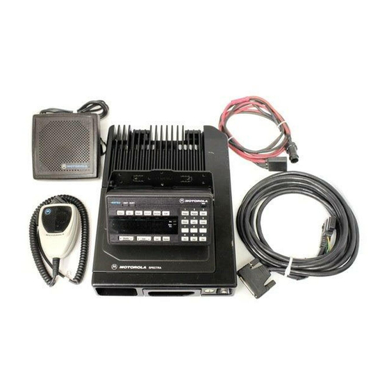
Motorola ASTRO Digital Spectra Manuel d'installation - Page 26
Parcourez en ligne ou téléchargez le pdf Manuel d'installation pour {nom_de_la_catégorie} Motorola ASTRO Digital Spectra. Motorola ASTRO Digital Spectra 32 pages. Fm two-way mobile radios
Également pour Motorola ASTRO Digital Spectra : Liste des pièces (13 pages)

Options and
Accessories
Installation for A4,
A5, A7, and A9 Model
Control Heads
VIP Output Connections
VIP Input Connections
20
PWR
Mode
Vol
MIC
HOME
Figure 17 Installing the Phone Button Key on
A4, A5, and A7 Model Control Heads
The vehicle interface port (VIP) allows the control head to operate outside
circuits and to receive inputs from outside the control head. There are
three VIP outputs which are used for relay control. There are also three
VIP inputs which accept inputs from switches. See the cable kit section for
typical connections of VIP input switches and VIP output relays.
The VIP output pins are on the back of the control head. The pin
information is shown in Figures 2, 4, and 5. Use these connections to wire
control relays. One end of the relay should connect to switched B+ voltage,
while the other side connects to a software controlled ON/OFF switch
inside the control head. The relay can be normally on or normally off
depending on the configuration of the VIP outputs. The control head has
three VIP output connections shown as follows:
Output Number
1
2
3
The function of these VIP outputs can be field programmed in the control
head. Typical applications for VIP outputs are external horn/lights alarm and
horn ring transfer relay control. For further information on VIP outputs, see the
control head programming manual.
The VIP input pins are on the back of the control head. These connections
control inputs from switches. One side of the switch connects to ground
while the other side connects to a buffered input to the control head. The
switch can be normally closed (NC) or normally open (NO) depending on the
configuration of the VIP inputs. The control head has three VIP input
connections shown as follows:
Input Number
1
2
3
INSTALL PHONE
BUTTON HERE
Phon
Scan
Sel
XMIT
BUSY
DIM
SW B+ Pin Number
18
19
35
Ground Pin Number
20
21
36
1
2
3
4
5
6
Sts
Msg
7
8
9
H/L
Mon
Dir
0
Rcl
Del
MAEPF-21423-O
On/Off Switched Pin
Number
2
21
34
On/Off Switched Pin
Number
4
3
37
