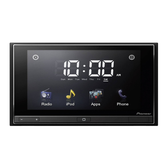
Pioneer AppRadio SPH-DA01 Manuel d'installation - Page 10
Parcourez en ligne ou téléchargez le pdf Manuel d'installation pour {nom_de_la_catégorie} Pioneer AppRadio SPH-DA01. Pioneer AppRadio SPH-DA01 40 pages. Display unit appradio
Également pour Pioneer AppRadio SPH-DA01 : Manuel d'utilisation (32 pages), Manuel d'utilisation (36 pages), Informations importantes pour l'utilisateur (24 pages), Mises à jour des microprogrammes (4 pages)

Section
02
Connecting the system
Connecting the control line cable
Green/white (BRAKE)
Used to detect the ON/OFF status of the
parking brake. This lead must be connected to
the power supply side of the parking brake
switch.
If this connection is made incorrectly or
omitted, certain functions of this product
will be unusable.
Note
The position of the parking brake switch vary
depending on the vehicle model. For details,
consult your authorized Pioneer dealer or an
installation professional.
WARNING
GREEN/WHITE LEAD AT POWER CONNECTOR IS
DESIGNED TO DETECT PARKED STATUS AND MUST
BE CONNECTED TO THE POWER SUPPLY SIDE OF THE
PARKING BRAKE SWITCH. IMPROPER CONNECTION
OR USE OF THIS LEAD MAY VIOLATE APPLICABLE
LAW AND MAY RESULT IN SERIOUS INJURY OR
DAMAGE.
10
En
Connection method
Clamp the lead of the power supply
side of the parking brake switch.
Clamp firmly with needle-nosed
pliers.
This product
Control line cable
Pink (REVERSE)
This is connected so that the this product can detect
whether the vehicle is moving forwards or
backwards. Connect the pink lead to the lead whose
voltage changes when the shift lever is put in
reverse. Unless connected, the sensor may not
detect your vehicle traveling forward/backward
properly, and thus the position of your vehicle
detected by the sensor may be misaligned from the
actual position.
Note
When you use a rear view camera, please make
sure to connect this lead. Otherwise you cannot
switch to the rear view camera picture.
Power supply side
Ground side
Parking brake switch
