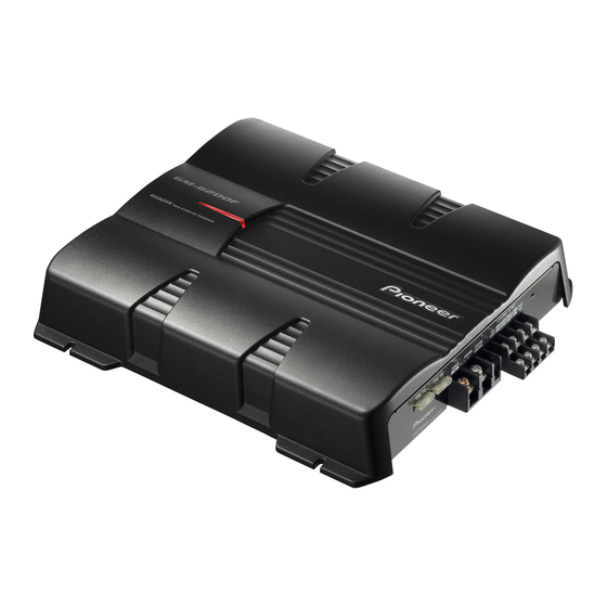
Pioneer GM-6200F Manuel du propriétaire - Page 7
Parcourez en ligne ou téléchargez le pdf Manuel du propriétaire pour {nom_de_la_catégorie} Pioneer GM-6200F. Pioneer GM-6200F 14 pages. Bridgeable four-channel power amplifier
Également pour Pioneer GM-6200F : Manuel du propriétaire (9 pages), Manuel d'entretien (33 pages)

- 1. Before Using this Product
- 2. Information to User
- 3. Product Registration
- 4. Setting the Unit
- 5. Gain Control
- 6. Power Indicator
- 7. Input Select Switch
- 8. Connecting the Unit
- 9. Connection Diagram
- 10. Connecting the Power Terminal
- 11. Connecting the Speaker Output Terminals
- 12. Using the Speaker Input
- 13. Example of Installation on the Floor Mat or on the Chassis
- 14. Specifications
- 15. Average Current Drawn
- 16. Additional Information
Connecting the Power Terminal
• Always use the special red battery and ground
wire [RD-223], which is sold separately. Connect
the battery wire directly to the car battery positive
terminal (+) and the ground wire to the car body.
1. Pass the battery wire from the
engine compartment to the interior
of the vehicle.
• After making all other connections to the
amplifier, connect the battery wire terminal of
the amplifier to the positive (+) terminal of
the battery.
Fuse (30 A)
Fuse (30 A)
Positive terminal
Insert the O-ring rubber
grommet into the vehicle
body.
2. Twist the battery wire, ground wire
and system remote control wire.
3. Attach lugs to wire ends. Lugs not
supplied.
• Use pliers, etc., to crimp lugs to wires.
4. Connect the wires to the terminal.
• Fix the wires securely with the terminal
screws.
GND terminal
Power terminal
Battery wire
Engine
Interior of
compart-
the vehicle
ment
Drill a 14 mm
(1/2 inch) hole
into the vehicle
body.
System remote
control terminal
System remote
control wire
Ground wire
WARNING
Failure to securely fasten the battery wire to the ter-
minal using the terminal screws could cause the ter-
minal area to overheat and could result in damage
and injury including minor burns.
Connecting the Speaker Output
Terminals
1. Expose the end of the speaker wires
using nippers or a cutter by about
10 mm (3/8 inch) and twist.
2. Attach lugs to speaker wire ends.
Lugs not supplied.
• Use pliers, etc., to crimp lugs to wires.
3. Connect the speaker wires to the
speaker output terminals.
• Fix the speaker wires securely with the termi-
nal screws.
Terminal screw
Speaker
output
terminal
Speaker wire
<ENGLISH>
