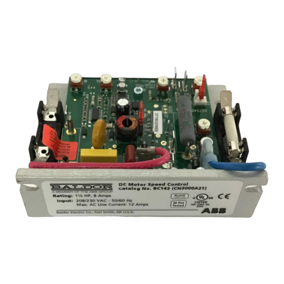
ABB Baldor BC142-5 Manuel d'installation et d'utilisation - Page 10
Parcourez en ligne ou téléchargez le pdf Manuel d'installation et d'utilisation pour {nom_de_la_catégorie} ABB Baldor BC142-5. ABB Baldor BC142-5 20 pages. Dc control

Permanent Magnet (PM) Motor Connection
Connect the motor armature positive lead (+) to Terminal A+ (Armature Fuse*) and the negative lead
(-) to Terminal A-. On Catalog Nos. BC142, BC142-5 and BC142-6, be sure Jumper J2 is set to the
corresponding motor voltage. Be sure the correct Plug-In Horsepower Resistor® is installed.
* Fuse holders and fuses not supplied with BC142-5.
Motor Field Connection (Shunt Wound Motors Only) see Figure 2-2
CAUTION! Do not connect motor armature leads to Terminals F+ and F-. Do not use Terminals F+ and F- for any
purpose other than to power the field of a shunt wound motor. Shunt wound motors may be damaged
if the field remains energized without armature rotation for an extended period of time.
Full Voltage Field
Connect the field positive (+) lead to Terminal F+ and the negative lead (-) to Terminal F-.
Half Voltage Field
For 50 Volt DC with 100 Volt rated armature, use Terminal L1 and F+.
Catalog
Input Voltage
No.
(VAC)
BC141
115
208 / 230
BC142
115
BC142-5
208 / 230
BC142-6
208 / 230
*Step-down operation.
PLUG-IN HORSEPOWER RESISTOR® & ARMATURE FUSE KIT*
The Plug-In Horsepower Resistor® and Armature Fuse are supplied as a prepackaged kit. Choose
the appropriate Plug-In Horsepower Resistor® and Armature Fuse based on motor horsepower and
voltage, see Table 2-4.
The Plug-In Horsepower Resistor® (supplied separately) must be installed to match the control to the
motor horsepower and voltage.
Install the Plug-In Horsepower Resistor® see Figure 2-2.
Notes:
1. The Plug-In Horsepower Resistor® is used to calibrate the IR Compensation and Current Limit
based on motor horsepower and voltage. The Plug-In Horsepower Resistor® eliminates the need
to recalibrate IR Compensation and Current Limit in most applications.
2. Be sure the Plug-In Horsepower Resistor® is inserted completely into the mating sockets.
8.2 Armature Fuse*
It is recommended that an Armature Fuse (supplied separately) be installed in the armature fuse
holder. Select the correct fuse. Fuses should be normal blow ceramic 3AG, MDA, or equivalent. The
optional Barrier Terminal Board (Catalog No. BC147) contains prewired AC line and armature fuse
holders. The Armature Fuse provides overload protection for the motor and control.
The Armature Fuse rating can be calculated by multiplying maximum DC Motor Current X 1.7.
* Fuse holders and fuses not supplied with BC142-5.
MN704
Table 2-3 Field Connection (Shunt Wound Motors Only)
Armature Voltage
(VDC)
0 -90
0 -180
0 -90*
0 -90
0 -180
0 -90*
Field Voltage
(VDC)
100
50
200
100
100
50
200
100
Terminal
Connections
F+, F-
F+, L1
F+, F-
F+, L1
F+, F-
F+, L1
F+, F-
F+, L1
2-3
