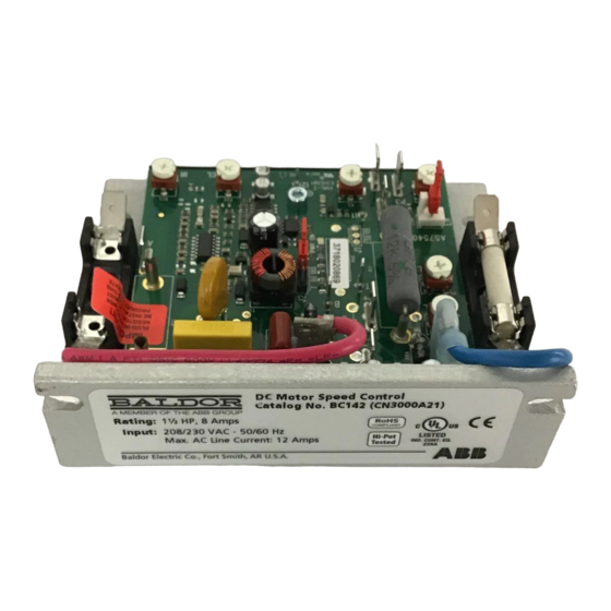
ABB Baldor BC142-5 Manuel d'installation et d'utilisation - Page 8
Parcourez en ligne ou téléchargez le pdf Manuel d'installation et d'utilisation pour {nom_de_la_catégorie} ABB Baldor BC142-5. ABB Baldor BC142-5 20 pages. Dc control

WARNING: Do not use this drive in an explosive environment. An explosion can cause serious or fatal injury.
This drive is not explosion proof.
MOUNTING INSTRUCTIONS
It is recommended that the control be mounted on a flat surface with adequate ventilation. Leave
enough room to allow for AC line, motor connection, and other wiring that is required. Care should
be taken to avoid extreme hazardous locations where physical damage can occur. When mounting
the control in an enclosure, the enclosure should be large enough to allow for proper heat dissipation
so that the ambient temperature does not exceed 40°C (104°F). If the optional Auxiliary Heat Sink
is used, mount the control in such a manner that there is unrestricted air flow through the heat sink
cooling fins. See Figure 2-1.
MOUNTING "A"
6 SLOTS
MOUNTING "B"
TAPPED 10-32
(3 PLACES)
3.00
76.2
FUSE HOLDER & FINGER-SAFE
COVER MOUNTING HOLES
1.50
38.1
TAPPED 6-32
(2 PLACES)
.75
19.1
1.75
44.5
Electrical Connections
Important Application Note: To avoid erratic operation, do not bundle the AC line and motor wires with
signal or control wiring. Also, do not bundle motor wires from multiple controls in the same conduit.
Use shielded cables on all signal wiring over 12 (30 cm). The shield should be earth grounded on the
control side only. Wire the control in accordance with the National Electrical Code requirements and
other local codes that may apply.
90 - 130 VDC
Max Motor
Motors
Current (ADC)
(Max HP)
6
12
16
AC Line Fusing
A 25 Amp AC line fuse is factory installed in the AC line fuse holder. It is recommended that a 12 Amp AC line
fuse be installed for motors rated 7.5 Amps DC or less. Fuses should be normal blow ceramic 3AG, MDA,
or equivalent. For USA 230 Volt AC lines, separate branch circuit protection for each line must be used. The
optional Barrier Terminal Board (Catalog No. BC147) contains prewired AC line and armature fuse holders.
MN704
Figure 2-1 Mechanical Specifications (Inches/mm)
3.64
92.5
.22
3.10
5.6
78.5
4.30
109
2.15
54.6
1.75
.64
.25
44.5
16.3
6.4
.18
4.6
Table 2-2 Minimum Supply Wire Size Requirements
180 Volt DC
Motors (Max
HP)
0.5
1
1
2
1.5
3
MAIN SPEED
POTENTIOMETER
(SUPPLIED)
3/8"
1/2"
1/4" ROUND
SHAFT
3/8-32
ANTI-
BUSHING
ROTATION
PIN
.13
3.1
P
.95
P
P
1
2
.44
24.1
11.1
1.25
31.8
Min Wire Size (Cu)
Maximum 50 Ft.
AWG
mm
16
1.3
14
2.1
12*
3.3*
Chapter 2
Installation
OPTIONAL AUXILIARY HEAT SINK
.98
24.9
CONTROL
7.00
178
3.11
(79.0)
5.63
142.9
6.25
159
1.25
3
31.8
1.38
34.9
Maximum 100 Ft.
AWG
2
14
12*
12*
.50
12.7
5.63
143
mm
2
2.1
3.3*
3.3*
2-1
